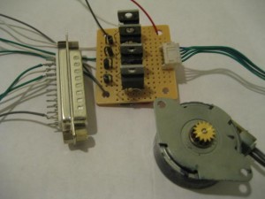
Using PC’s parallel port is a convenient way to control a stepper motor. For unipolar stepper motors, up to two motors can be controlled with the 8bit data line.
The standard way of connecting a unipolar stepper motor to the parallel port is to use a Darlington driver such as ULN2003 and there are already many examples out there on how to do this. In this post, I will show you how to build a simple stepper motor driver using discrete MOSFETs.
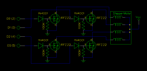
In the circuit diagram below, you will find that the four power MOSFETs are used as switches for each coil in the stepper motor (the stepper motor I used in this example is a MITSUMI M35SP-9. In theory, any uni-polar stepper motors should work with this circuit). A pull-down resistor is attached to the gate of each MOSFET. This is important as otherwise the interference from the port would prevent the MOSFET from switching reliably.

The benefit of using discrete MOSFET is that they can handle extremely high current loads. Using IRFZ22, the coil current can be as high as 10 Amp.

The following C code sets the data port (pin 2, 3, 4, 5) to high in order so that the stepper motor would rotate clockwise. If you want the motor to rotate counter-clockwise, simply change the output order to 8,4,2,1.
#include <sys/io.h>

#define PAR_PORT 0x378

void main()
{
	while (1)
	{
		outb(1, PAR_PORT);
		outb(2, PAR_PORT);
		outb(4, PAR_PORT);
		outb(8, PAR_PORT);
	}
}

