Field strength meter is extremely useful when working with RF devices. It can be used to quickly diagnose whether a transmitter circuit is working, and can be used to detect RF signals in the environment.
The simplest field strength meter could be built with a tuned LC circuit and a germanium diode, just like the way of a building a crystal radio except replacing the ear piece with a high sensitivity current meter. While this approach fits the needs of most simple applications, it has a pretty narrow frequency range (~100 MHz) and requires tunning the LC circuit to the correct frequency before measurements can be made and the design can become complicated if wider frequency range tuning is desired.
Another option is to use an RF detection chip. Most of such chips (from Linear Technologies, Maxim and Analog Devices) offer a very broad testing range and have much higher sensitivity and accuracy than a simple diode signal detector can offer. Here I will use Linear Technologies’ LT5534 RF detector chip as the field strength meter’s front end. Similar circuits can be build with other RF detection chips as well, depending on the types of the specific application.
LT5534 can detect RF signal from 50MHz all the way up to 3GHz, which covers most of the spectrum one typically uses. If your frequency spectrum is significantly different, you may check out the other RF detection chips the above mentioned companies offer.
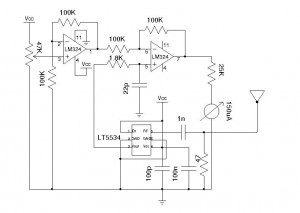
Here is my design of the field strength meter:

The core detector circuit is almost identical to the reference design. The LM324 op-amp forms a differential amplifier with a gain of 2. The main purpose of this differential amplifier is to provide the ability to “zero” the meter reading or adjust the sensitivity of the detector. Since the differential op-amp’s output is proportional to the voltage difference between the output of LT5534 and the wiper voltage of the potential meter, we can adjust the potential meter to set the reference point (i.e. zero reading) for the environment. Also, by raising the wiper’s potential, it would take a higher output from the RF detector for the differential op-amp to register an input voltage and thus effectively lowered the sensitivity of the detector.
The output bandwidth of LT5534 is tens of MHz, since we do not care about the signal details in this particular application, the relatively low bandwidth LM324 has no impact on performance. The above circuit uses a 5V regulated power supply.
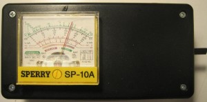
The following picture shows the meter reading when a cell phone is near by (cell phone is not shown):

The 150 uA meter here was taken from an old analog multi-meter.

