In my previous post, I showed a simple optical encoder circuit that is TTL compatible. The main drawback of the circuit is that it does not provide enough resolution since the encoder is only triggered when the mounted mirror is aligned. So this design is more suitable for movement detection (i.e. whether the model vehicle is moving or not) rather than speed detection. While the resolution can be increased by carefully designing the reflective surface (i.e. multiple reflective stripes), but the implementation becomes much more difficult.
Most optical wheeled mice has an encoder built into the wheel mechanism and provide a relatively high resolution (several dozen signals per rotation). Some of the mouse wheel mechanism use mechanical encoders, but most designs nowadays use optical encoders. Either type of encoder should work for the purpose of wheel rotation detection, but for higher reliability, optical encoder should be a better choice.
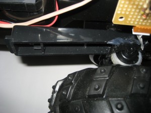
An easy way to interface the mouse wheel encoder with model vehicle wheel is to use some kind of friction drive mechanism as below:

Use the method above, no wheel modification is required. As an added benefit, the encoder resolution is enhanced further due to the larger diameter of the driving wheel.
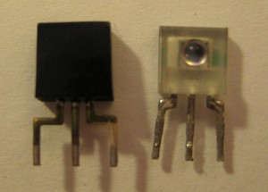
The picture below shows a couple of photo sensors used in optical encoders commonly found in optical mice.

These photo sensors typically contain two common emitter photo transistors (see below). The purpose of this configuration is to detect both the rotation speed and the rotation direction. If we don’t care about the direction information, either one of the output can be used.

The Arduino code for this optical encoder is identical to what I used in my last post. Every time a signal is received, the interrupt function wheelEncoderISR is called. Since the encoder resolution is very high, we can use a timer interval (i.e. every 50ms) in conjunction with the interrupt routine to capture the number of pulses received within this time (for 50ms interval, the pulse count range from 0 to more than 100 using the configuration in the first picture). Using this pulse-count information, model vehicle’s speed can be controlled easily.
void setup() {
  attachInterrupt(0, wheelEncoderISR, FALLING);
}

void wheelEncoderISR() {
...
}

