I wanted to be able to check my web server’s statistics periodically but did not want having to log on ever time when I wanted to do so. The simplest way to achieve this is to have the computer monitor on and run a server statistics program that outputs the information onto the screen. There are two issues associated with this approach however: the first problem is that a dedicated monitor will be needed which is not typical in a server configuration. And the second issue is that a monitor would waste considerably amount of power when powered on 24/7.
So I decided to build a low power consumption auxiliary display that would enable me to show some of the server statistics. The idea here is to use a microcontroller circuit that displays information sent from the server via a serial link. I used an ATmega328p mciro-controller and used Arduino library for the MCU programming.
In my design, the server statistics are gathered via a shell script (Linux):
#! /bin/sh

############### info.sh ####################

#IP Address
wget -q -O - checkip.dyndns.org|sed -e 's/.*Current IP Address: //' -e 's/<.*$//' > /home/kwong/scripts/data.txt

#Hit Counter
wc -l /var/log/apache2/access.log | echo 'Hits:' `awk 'BEGIN {FS="[ ]"} {print $1}'` >> /home/kwong/scripts/data.txt

#Date Time
date '+%a %H:%M%n%m/%d/%Y' >> /home/kwong/scripts/data.txt

#Average Load
uptime | echo 'Load:' `sed -e 's/.*load average: //' -e 's/,.*$//'` >> /home/kwong/scripts/data.txt
#Uptime
uptime | echo 'Up:' `sed -e 's/.*up.//' | awk 'BEGIN {FS=","}{print $1 $2}' | sed -e 's/.days\?/d/'` >> /home/kwong/scripts/data.txt

#invoke the c program to send the information over the serial port
/home/kwong/scripts/multidisp
As you can see, the information I gathered includes the following:
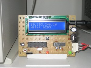
- Server’s external IP address (I use dynamic DNS service, so this is useful as the external IP address changes periodically)
- Hit Counter (I rotate my apache logs on a daily basis, this would show me how many hits I’ve got so far for a given day)
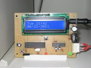
- Date and time
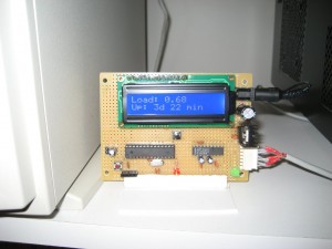
- Server’s average load for the past minute.
- Uptime since last reboot.
The statistics are then saved to a file so that it can be retrieved by another program to transmit to the microcontroller at a predetermined time interval. In the script above, I outputted six lines of statistical information. But you can adapt it to including more or less information depending on your need.
In order to periodically refresh this information, I setup a crontab for the script to run every minute.
# m h  dom mon dow   command
* * * * * /home/kwong/scripts/info.sh
Now after we have gathered the information, we need to send it to the microcontroller for display. I wrote the following C code to send the information recorded in the file to the serial port:
#include <stdio.h>
#include <stdlib.h>
#include <unistd.h>
#include <termios.h>
#include <fcntl.h>

int  fd;

void readFile()
{
    FILE *fp;
    char line[80];

    fp = fopen("/home/kwong/scripts/data.txt","r");

    if (fp == NULL)
    {
        printf("File doesn't exist\n");
        exit(-1);
    }

    while(fgets(line, 80, fp) != NULL)
    {
        unsigned long l = strlen(line);
        unsigned long maxIdx = l;
        char c = ' ';

        if (maxIdx > 16) maxIdx = 16; //16 characters per line max

        int i = 0;
        for (i = 0 ; i < maxIdx; i++)
        {
            if (line[i] != 10 && line[i] != 13)
            {
                c = line[i];
                write(fd, &c, 1);
            }
        }

        for (i=0 ; i < 16 - maxIdx + 1; i++) //pad each line to 16 characters
        {
            c = ' ';
            write(fd, &c, 1);
        }

    }

    fclose(fp);
    close(fd);
}

void initSerial()
{
    struct termios options;

    fd = open("/dev/ttyS0",O_RDWR | O_NDELAY | O_NOCTTY);
    fcntl(fd, F_SETFL, FNDELAY);

    tcgetattr(fd, &options);

    options.c_cflag     |= CREAD;
    options.c_lflag     &= ~(ICANON | ECHO | ECHOE | ISIG);
    options.c_oflag     &= ~OPOST;

    options.c_cflag &= ~PARENB;
    options.c_cflag &= ~CSTOPB;
    options.c_cflag &= ~CSIZE;
    options.c_cflag |= CS8;

    options.c_cflag &= ~CRTSCTS;
    options.c_iflag |= (IXON | IXOFF | IXANY);

    //set baud rate
    cfsetispeed(&options, B9600);
    cfsetospeed(&options, B9600);

    tcsetattr(fd, TCSAFLUSH, &options);
}

int main()
{
    initSerial();
    readFile();

    return 0;
}
To simplify the coding on the mciro-controller side, I padded each line to 16 characters (that’s the number of characters can be displayed on each line on the LCD). Also, the contents of the file (6 lines, 16 bytes each) are sent to the MCU all at once, it is up to the code at the MCU side to decide which lines to display. This way, we only need one-way serial communication (i.e. from computer to the MCU).
Alternatively, you could use the MCU to send instructions to the computer via serial port and let the server side code decide what information to send back to the MCU depending on the instructions received. The main benefit of this latter approach is that information is sent on-demand and is especially useful when there is a large amount of information collected on the server. Since the RAM space on a typical MCU is quite limited, sending only the information needed at any given time may be the only viable choice in this situation.
But in this application, there are maximum of 96 bytes worth of information and can be stored in memory with no issues on an ATmega328, so I chose to use the first approach (sending all the information at once) to simplify coding.
For the MCU board I used an LT1780 RS232 to UART converter chip for the RS232 to serial conversion (see my previous post). When using a dedicated serial port driver no other software is needed. The Arduino code is shown below:
#include <LiquidCrystal.h>

const int pinRS = 3;
const int pinEn = 4;

const int pinD4 = 5;
const int pinD5 = 6;
const int pinD6 = 7;
const int pinD7 = 8;

const int pinSwitch = 9;
const int pinLED = 13;

int i = 0;
unsigned long opt = 0;
int currentLine = 0;
char messages[6][16];
bool ledOn = false;

LiquidCrystal lcd(pinRS, pinEn, pinD4, pinD5, pinD6, pinD7);

void setup() {
  pinMode(pinSwitch, INPUT);
  digitalWrite(pinSwitch, HIGH);

  pinMode(pinLED, OUTPUT);
  digitalWrite(pinLED, LOW);

  lcd.begin(16, 2);
  Serial.begin(9600);
}

void loop() {
  if (Serial.available() > 0) { //in transmission mode

    int l = 0;
    currentLine = 0;
    while (Serial.available() > 0) {
      ledOn = ~ledOn;

      //toggle LED indicating data being sent
      digitalWrite(pinLED, ledOn);

      messages[currentLine][l] = Serial.read();
      l++;

      //altogether 6 lines are transmitted,
      //each line has 16 characters (space padded)
      if (l == 16) {
        l = 0;
        currentLine = (currentLine + 1) % 6;
      }
    }
  }
  else { //in display mode
    ledOn = false;
    digitalWrite(pinLED, ledOn);

    //display the first line
    lcd.setCursor(0, 0);
    for (i = 0; i < 16; i++)
      lcd.write(messages[opt * 2][i]);

    //display the second line
    lcd.setCursor(0, 1);
    for (i = 0; i < 16; i++)
      lcd.write(messages[opt * 2 + 1][i]);

    //changes the lines being displayed in the message buffer
    //when opt == 0, line 0, 1 are displayed
    //when opt == 1, line 2, 3 are displayed
    //when opt == 2, line 4, 5 are displayed
    if (digitalRead(pinSwitch) == 0) {
      delay(25);
      if (digitalRead(pinSwitch) == 0) {
        Serial.println(opt);
        opt++;
        opt %= 3;
      }
    }

    delay(250);
  }
}
In the main loop, the MCU sits passively waiting for either serial port inputs or the push of a button (attached to pin 9). At the end of each one minute interval the server side code refreshes and the latest 96 bytes of data is sent over to the MCU via the serial port. The 96 bytes are parsed into 6 lines of data, 16 bytes each line, and stored into the messages buffer.
If the button attached to pin 9 is pressed, the counter opt is incremented and result modulo 3 (i.e. 0, 1, 2) is then used to choose which set of the lines to display (the 6 lines are divided into 3 sets since I am using a 16×2 LCD).
The three pictures below show this auxiliary display in action:


