Over the years, I have gathered quite a few NTC and PTC thermistors. But most of them are unmarked so it would be difficult to use them in an accurate way without knowing the parameters. So I decided to build a simple circuit that can be used to trace the temperature-resistance curve, and the parameters can then be estimated using the measured data points.
Here, I will show you a simple circuit that I designed that can be used as an front end for such measurements. Outputs from this circuit can be inputted into an MCU (such as the popular Arduino) for further analysis.
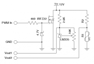
The circuit is shown below:

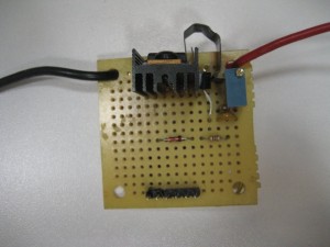
Here the MOSFET (IRFZ22) is used as an active load. The gate voltage is limited to 4.7V by the Zener diode (e.g. 1N4732). This is important as according to IRFZ22’s datasheet, by limiting the gate voltage to 4.7V, the maximum drain to source current (Ids) is limited to roughly 2 Amp. In principal, pretty much any power MOSFET can be used for this purpose, as long as Vgs is clamped to ensure that the MOSFET operates within the safe limit. A small heat sink is used as the heating surface. A PWM signal is used to control the gate. By adjusting the PWM duty cycle, the thermal dissipation of the MOSFET can be controlled and thus the heatsink temperature can be varied programmatically.
A precision temperature sensor LM335 is clamped onto the heatsink (see picture below) so the surface temperature can be monitored. When used with a closed loop control (e.g. PID control) the heatsink surface temperature can be controlled precisely.

To measure the parameters of an unknown thermistor (either PTC or NTC), choose an appropriate R2 so that the voltage change across the thermistor under measurement is maximized over the desired temperature range and at the same time the self-heating effect is minimized.
The thermistor temperature-resistance curve can be obtained as follows:
- Attach the thermistor to be measured near the LM335 sensor. The surface of the thermistor should be firmly attached to the heatsink surface to ensure that the temperature reading from LM335 is the same as the temperature of the thermistor.
- Gradually increase the PWM duty cycle of the control signal so that the temperature reading from LM335 slowly increases (e.g. 1 degree per minute). The temperature has to be changed slowly so that we can ensure that both LM335 and the thermistor are at the same temperature.
- Record the temperature via Vout1 and the thermistor’s resistance via Vout2 using an MCU.
Using this circuit, the control temperature can be safely raised to about 250 Fahrenheit (121 Celsius) which should give wide enough of a range for most thermistor measurements.
I will show a few examples in a later post.

