I have used DS3232 RTC (real-time clock) in many Arduino based projects before. DS3232 utilizes a temperature compensated oscillator, which makes it far more accurate than devices like DS1307. In this blog post, I will give some code examples on implementing a digital clock using DS3232 and the TI MSP430 Launchpad.
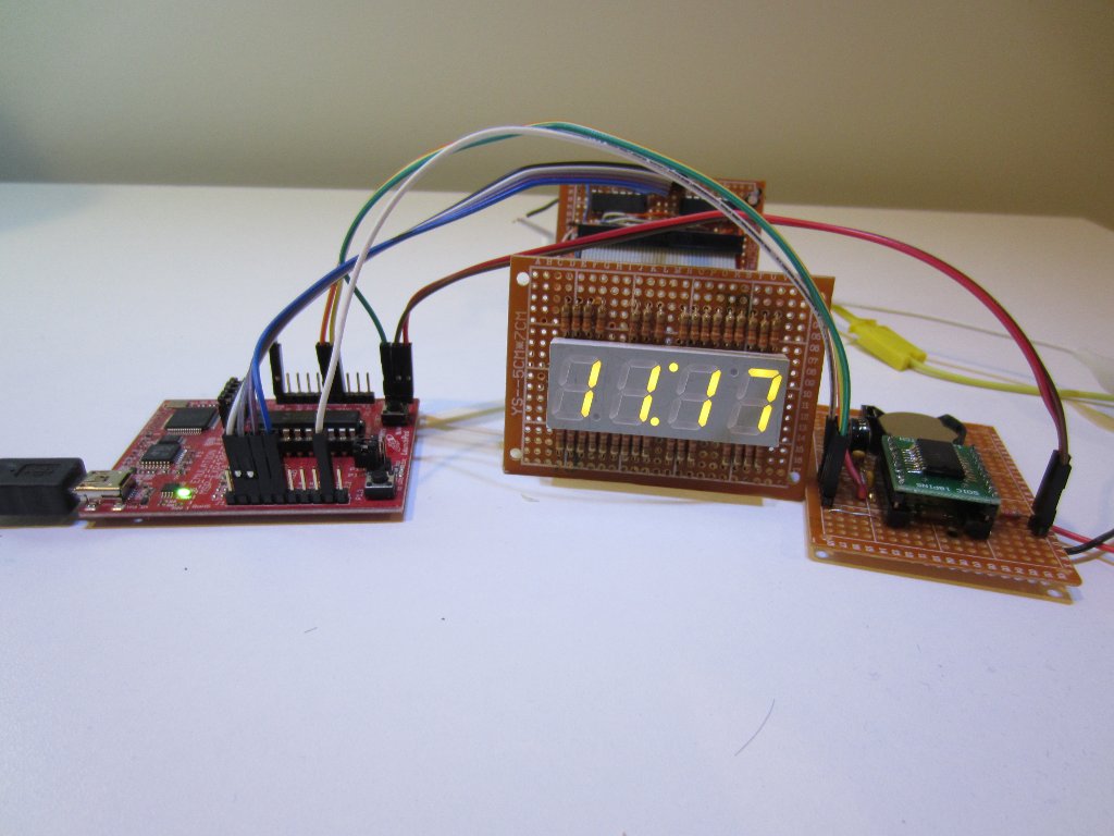
The following picture shows the project setup. The RTC breakout board on the right is connected to the Launchpad via I2C pins (P1.6 for SCL and P1.7 for SDA respectively) and pin P1.0 through P1.3 are used for the OE, Latch, Clock and Data pins on the 74HC595 7-segment display board. As I discussed before, you may need to remove the jumper on P1.6 for the I2C to work properly. The MCU chip I used is an MSP430G2452, but you could use other MCUs that supports I2C in the value line as well.
If you are new to implementing I2C using MSP430G2 devices, you can take a look at my earlier tutorial first.
The display is driven using four 74HC595 with a LTC-5851Y 4 7-segment display. Because there are many variations in these multi-digit 7-segment displays, you may need to modify the actual display masks to match up your particular display. You can take a look at one of my earlier examples for more details. The code listed below was compiled and tested using TI’s CCS 5.3.

