Neal from SchmartBoard sent me an MSP430F5172 development board to check out. This board, according to the website, was co-designed with the University of Colorado for itw educational needs. It is actually just a breakout board for TI’s MSP430F5172 mixed signal microcontroller with added power regulator circuitry and a conveniently positioned JTAG connector.
While there isn’t anything fancy about this board, it never the less is a quite capable development kit. If you have played around with TI’s Launchpad you’d appreciate the added capabilities of the onboard MCU. Like the MSP430G2 series, MSP430F5172 is a 16-bit MCU. But it has a lot more flash memory and IO pins on top of a much faster processing core. So it is suitable for using in more complex projects where more control pins are needed.
One thing nice about TI’s MCU lineup is that you can use Code Composer Studio for all your project development work. So if you have used CCS with other chips or TI’s Launchpad, you will be able to get started in almost no time. But unlike the MSP430 Launchpad where an intergraded programmer/debugger is provided on the experiment board for easy programming, you will need to use a JTAG programmer to upload your hex file onto the MSP430F5172 board.
MSP430F5172 programming via BSL
Since I don’t have a compatible JTAG programmer, I had to find an alternative way to program the chip.
Fortunately, most of the MSP430 devices can be programmed using the built-in BSL (Bootstrap Loader). And TI’s MSP430G2 Launchpad has a convenient utility which turns a Launchpad into a BSL programmer. More detailed information on the Launchpad BSL programming can be found here.
Since BSL is a feature that people often overlooked and instructions are pretty sketchy on the web, I thought I would give a little bit more detail on this using the MSP430F5172 development kit from SchmartBoard as an example.
The first step is of course to load the BSL firmware onto your Launchpad so that it can be used as a programmer. To do this, you will need to download the zip file from TI’s site. After unzipping it, open the project located in LPAD_BSL_INTERFACE\Firemware\Projects\CCS\LPAD_BSL_INTERFACE using CCS. Since the project is statically linked, you will need to make sure not to click “Copy projects into workspace” when prompted. It appeared that the project was created with an older version of the CCS and when I opened it with CCS 5.2.1 it complained that it could not find lpad_bsl_int.c. An easy solution to this was to re-include that file manually (LPAD_BSL_INTERFACE\Firmware\Source\lpad_bsl_int.c). After this quick fix, you should be able to compile the firmware with CCS and upload it onto your Launchpad. The MCU I used on the Launchpad is MSP430G2231, but pretty much all chips in the MSP430G2 family can be used for this purpose.
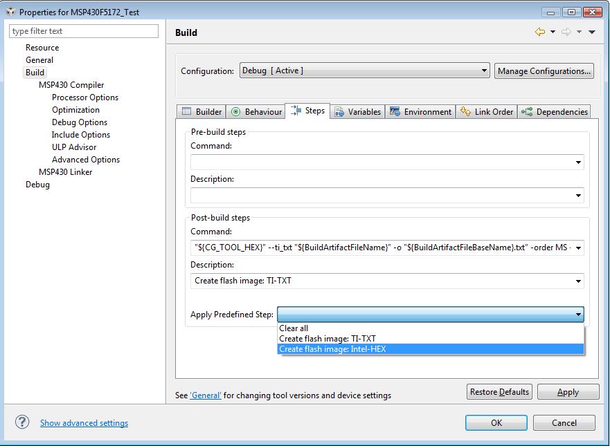
The second step is to prepare the HEX file for uploading to the target device (in this case it’s the MSP430F5172). By default, CCS does not create a HEX file during compilation, but this can be added as a post-build step (see screenshot below).
Now we are ready to hook up the Launchpad and the MSP430F5172. The connections should be made according to TI’s documentation but I will include the connection mappings here for clarity (Note, the pin out in TI’s slaa535a is for the 40-pin QFN package which is slightly different for the 38 TSSOP version used on the SchmartBoard dev kit), the dev board’s pinout is on SchmartBoard’s site):
Launchpad    - SchmartBoard Dev Kit
MSP430G2231  - MSP430F5172

J6.1 (VCC)   - Pin 1 (VCC)
J6.3 (GND)   - Pin 4 (GND)
J2.14 (P1.6) - Pin 37 (P3.5)
J2.15 (P1.7) - Pin 38 (P3.6)
J1.6 (P1.4)  - Pin 36 (/RST)
J1.7 (P1.5)  - Pin 35 (TEST)
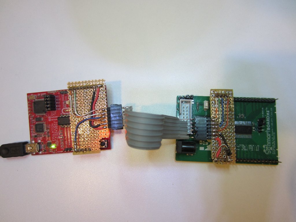
If you use BSL a lot, it might be worthwhile to build a dedicated adapter for it like what I have done below:
Once the Launchpad and the target board are connected, we can connect the Launchpad to the PC via a USB cable. Note that I used the 3.3V Vcc from the Launchpad to power the MSP430F5172 directly, bypassing the on-board regulator. If everything is connected correctly you should see both the red and green LEDs on the Launchpad light up. If they are blinking, then you will need to double check your connections.
To upload the firmware, we will use BSL_Scripter.exe supplied with the LPAD_BSL_INTERFACE utility (under LPAD_BSL_INTERFACE\TestScripts\Exe). Depending on what target chip you are using, you can take a look at the examples provided in the TestScripts folder to see how the scripting is done. Each BSL script (script.txt) contains multiple lines of commands.
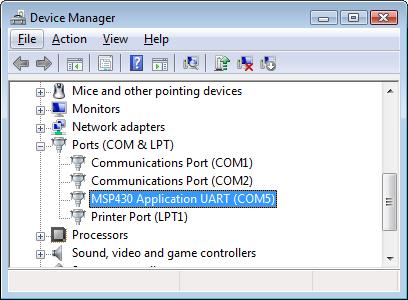
The following list is what a BSL script looks like. You will need to replace the actual COM port number you are using (via device manager, see image below) in place of COM5. The highlighted line is where the program firmware is sent.
MODE 5xx COM5
VERBOSE
MASS_ERASE
RX_PASSWORD
RX_DATA_BLOCK MSP430F5172.hex
RX_DATA_BLOCK BOR.txt
The COM port should be set as the following: baud rate 9600, 8 data bits, 1 stop bit, no parity and no flow control.
To run the BSL loader, simply issue the following command under command prompt:
BSL_Scripter.exe script.txt
When running in verbose mode, you should see the message “DONE” after each step. The last command (RX_DATA_BLOCK BOR.txt) resets the target device. For some reason, this step always returns “FAIL”. But it actually works because the LED on the SchmartBoard will start blinking once the code is uploaded and the device is reset. If this line is omitted however, the LED will not blink until we reset the board. In any event, the BOR command is not strictly necessary for the BSL process to work properly.
Note
As many people have mentioned, this particular chip can also be programmed using Spy-bi-wire (which I had shown an example before). This post was just showing yet another method to program this chip.

