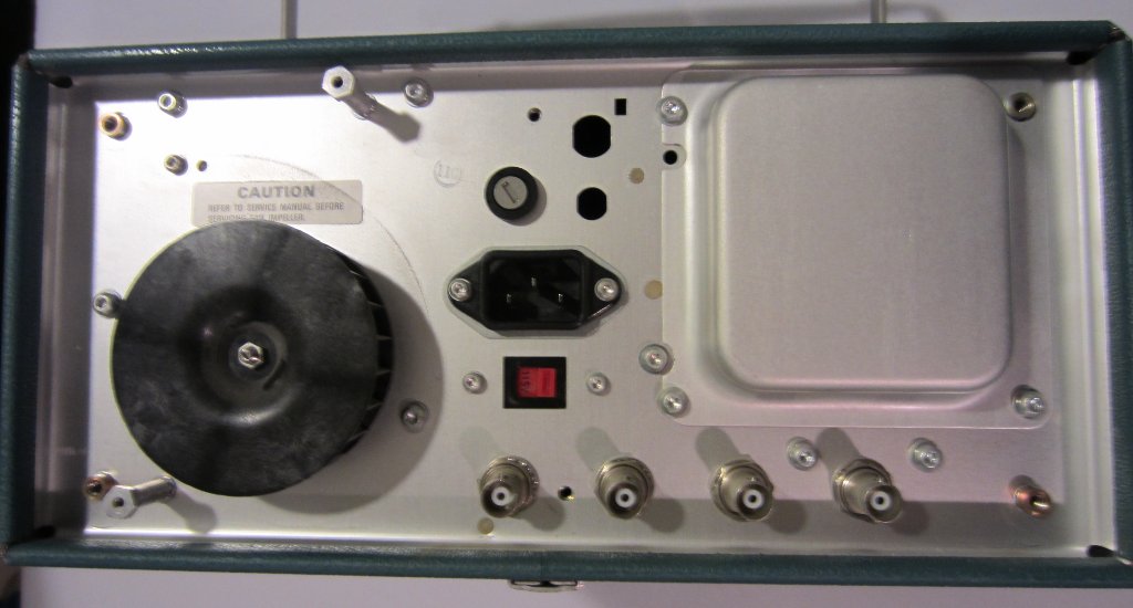
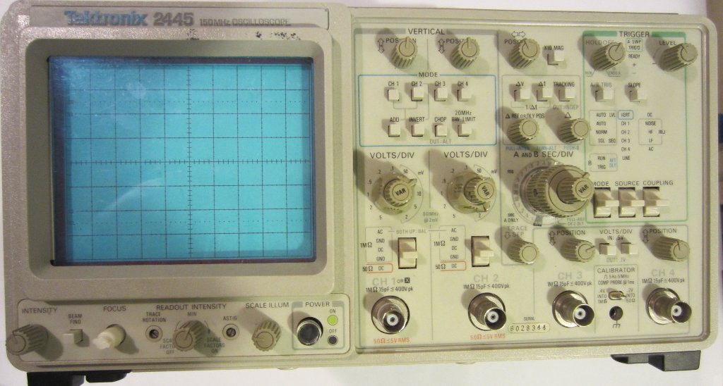
I bought an old Tektronix 2445 150 Mhz oscilloscope on eBay the other day. It was listed under “For Parts/Not Working” condition. Since the pictures in the auction listing suggested that the scope powers up and shows traces on all channels, I thought I would get it and fix it up.
A couple of days later, the oscilloscope arrived. The unit looked a bit dusty and was missing a knob (which I already knew) but overall it was in pretty good shape, presumably it had been left in storage for quite some time. I also noticed is that HOLD OFF and LEVEL knobs were very loose, but they seemed to turn just fine. So after some cleaning I decided to power it up and check out what was wrong with the scope.
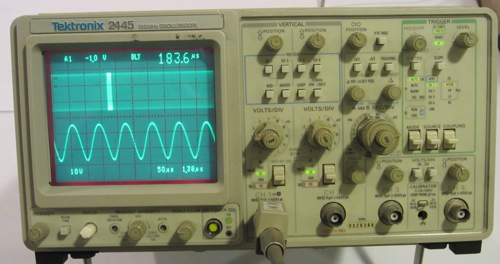
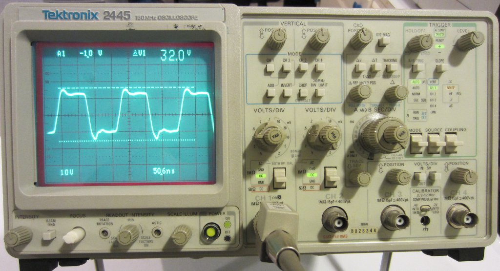
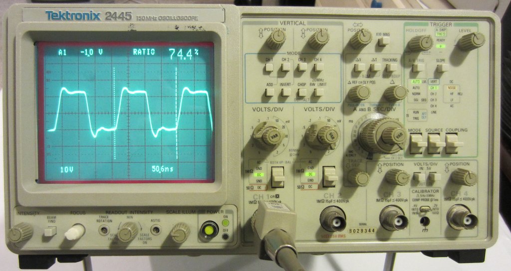
As it turned out, everything seemed to be working just fine! Occasionally the screen readouts would flicker on and off but I was pretty sure that was just a loose cable connection somewhere. The loose knobs were kind of annoying though as I had to press them down pretty hard to turn the underlying potentiometers. So my next steps were to investigate the screen readout issue and also see whether I could fix the two loose knobs. In the mean time, I thought I would snap a few pictures and take a closer look inside.
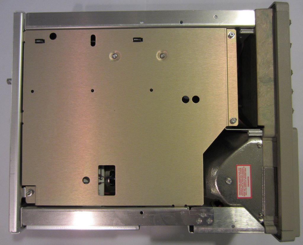
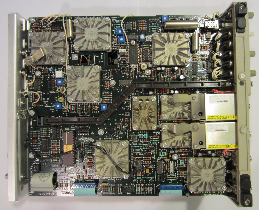
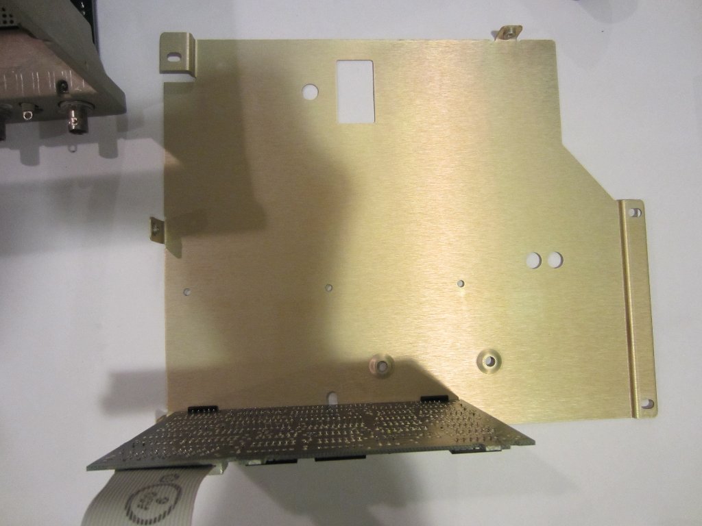
After removing the four screws on the back, the whole cover slid off easily. Since Tektronix 2445’s main board is at the bottom, care must be taken when taking off the cover to avoid accidentally damage the parts or wiring on the main board. The top two pictures below were taken from the top and the CRT side. Besides a few access wholes for calibration and service adjustments, nothing can be easily accessed. This is largely due to the space constraint however.
 |
 |
 |
 |
Fortunately, the front panel assembly comes out rather effortlessly after removing the cover frame. The whole control assembly can be pushed out afterwards with a bit of force as the unit is held in the frame with some sort of springy metal tabs that also serve as grounding contact. I forgot to take a picture of the control assembly when it was out as I was too concentrated on fixing the loose knob issue.
After removing the front panel assembly, it became clear what went wrong with the loose knobs. Apparently, the two potentiometer shafts had snapped and broken off! One way to fix this problem is to replace the these affected potentiometers. Since I don’t have any spares (these were probably specifically made for Tektronix back then and any spare parts will likely be very expensive), I carefully super glued the broken shafts together. This was a rather delicate process as I dare not let any glue get in between the potentiometer and the shaft, otherwise I wouldn’t be able to turn the shaft afterwards. Fortunately, the whole process went without a glitch and after an hour both HOLD OFF and LEVEL knobs were fixed.
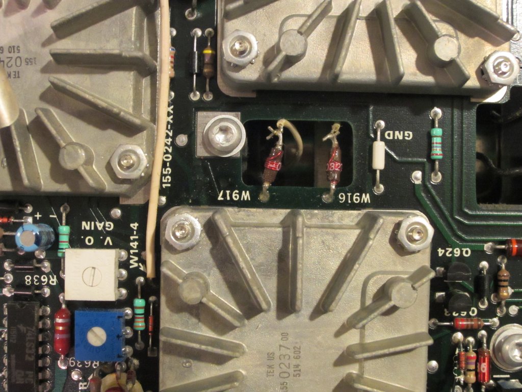
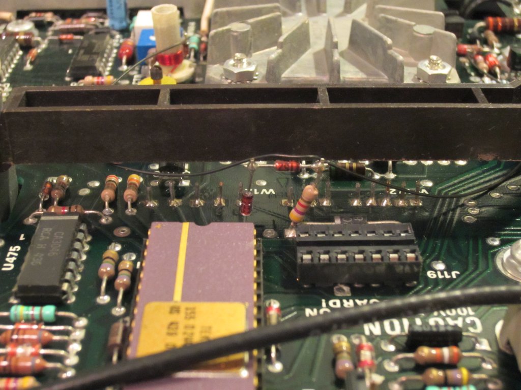
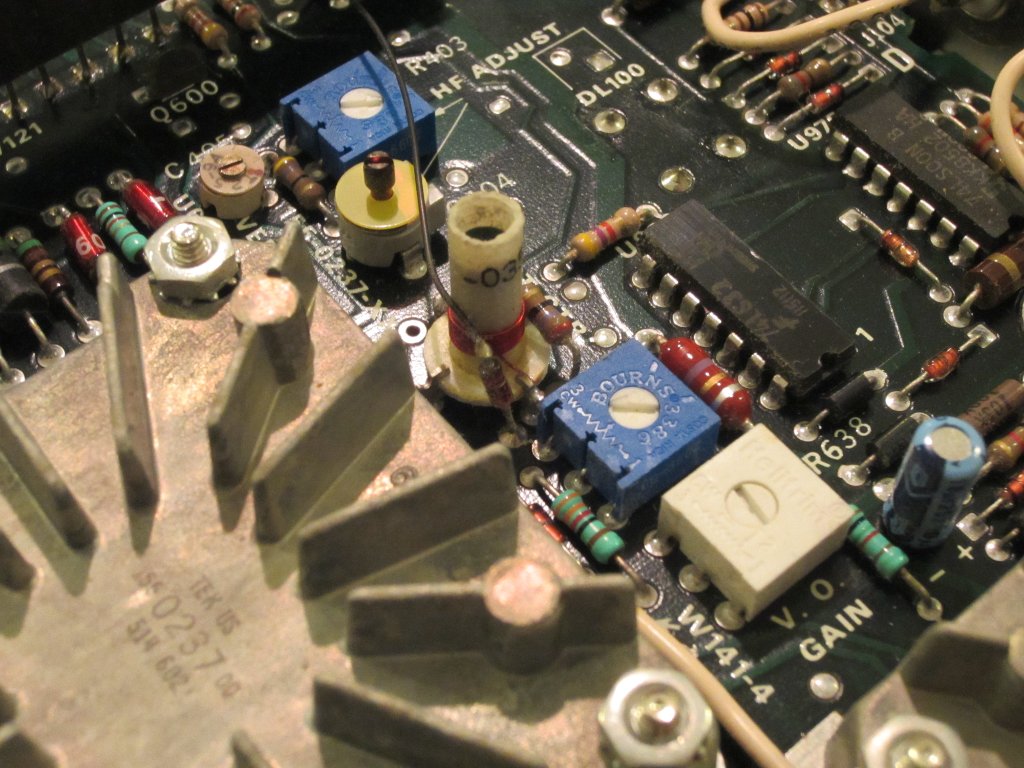
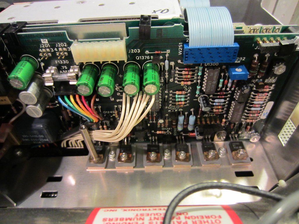
As mentioned earlier, the main circuit board is located at the bottom of the oscilloscope. The layout is relatively clean but there are quire a few flying wires and intricate connections. In the bottom left picture below, you can see a diode was soldered directly onto the leads of a resistor and another diode. And in the picture to the right, you can see that a choke with only one pin soldered on the board, the other side is connected to a wire directly. I am not quite sure if these were originally done this way or was modified during servicing afterwards.
|
|
|
|
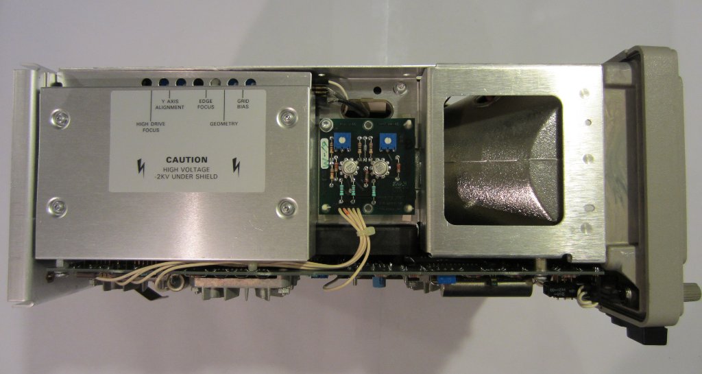
Under each of those finned aluminum cover is a custom hybrid module made by Tektronix. As many people already know, if one of these modules fails, pretty much the only solution is to resort to a donor module from another scope of the same kind as these modules have been discontinued long time ago.
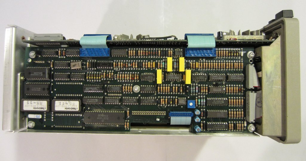
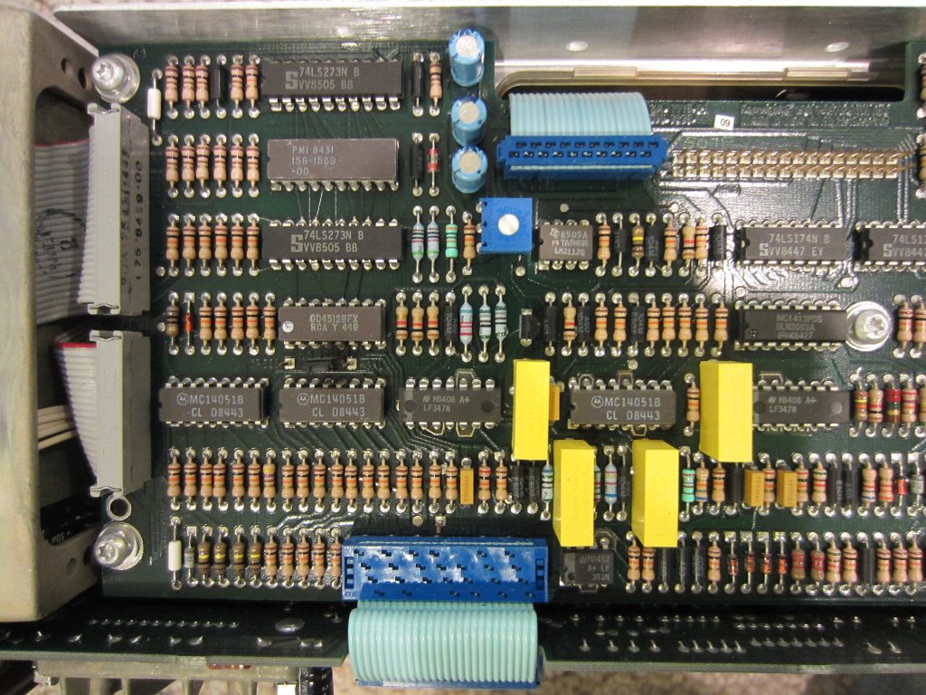
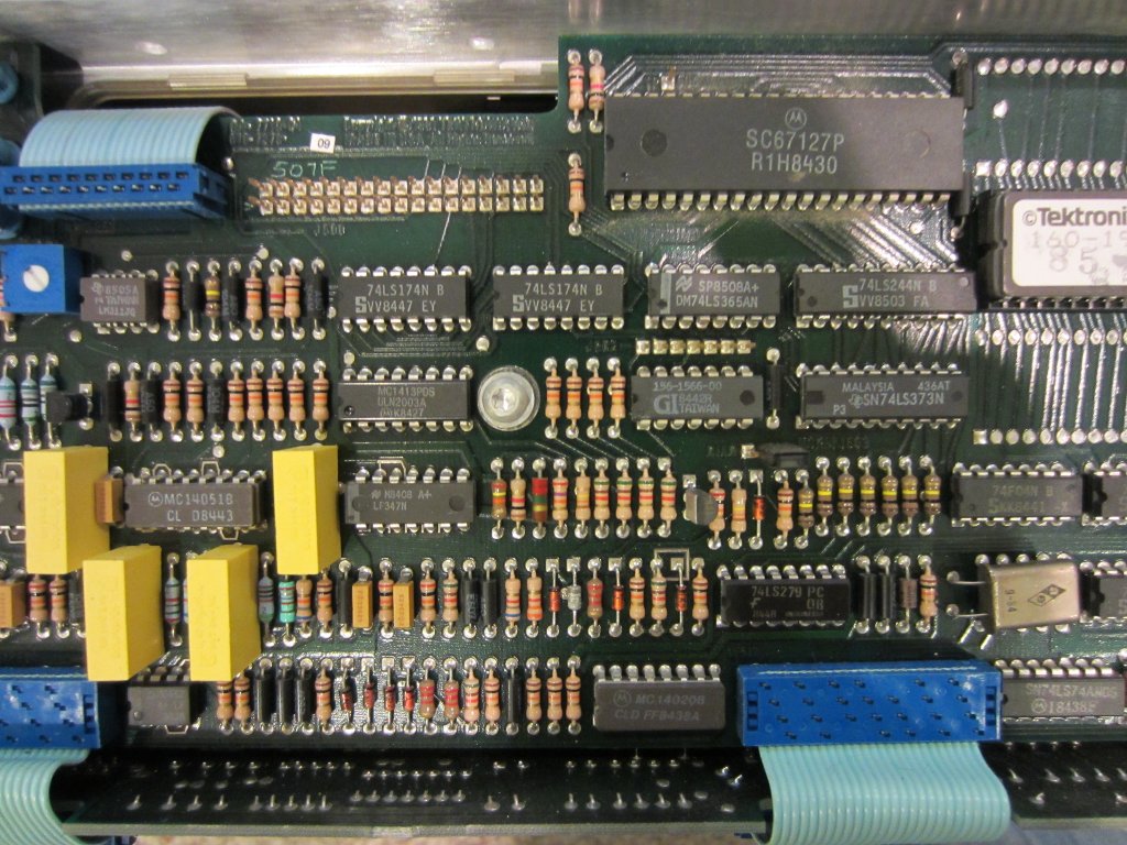
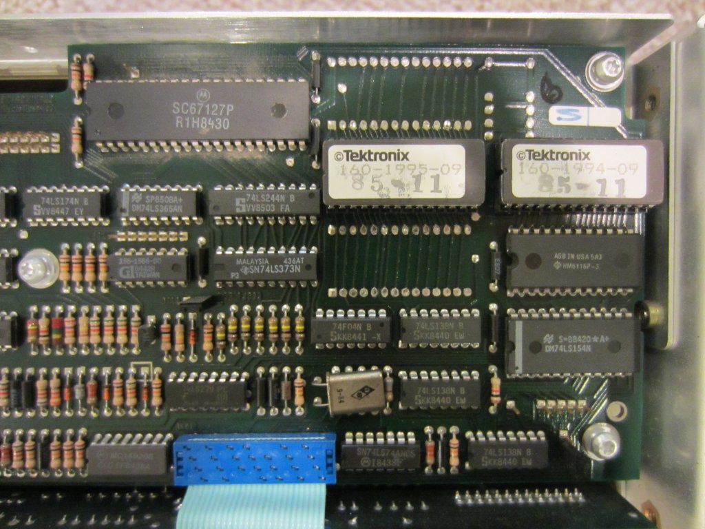
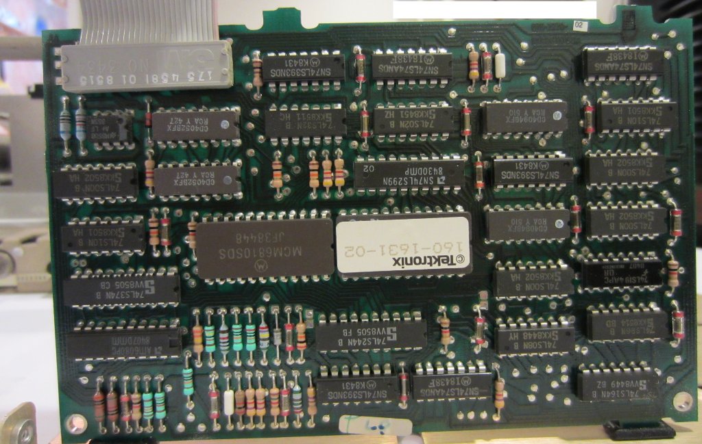
On the other side of the oscilloscope is the control board (see pictures below), which is connected to the rest of the system (e.g. the front panel control module, readout board, power supply, etc.) via ribbon cables.
|
|
|
|
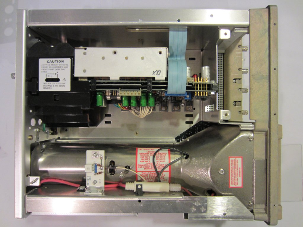
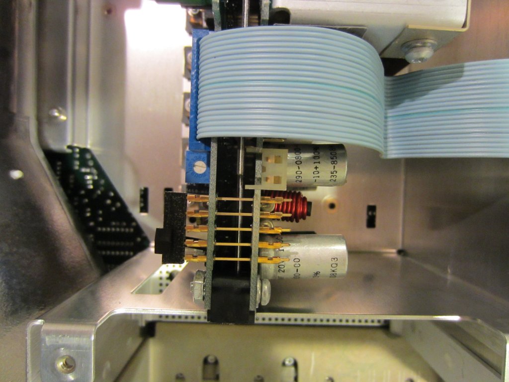
The board that hosts the readout circuitry (see below) is mounted on the top cover and can only be accessed after removing the top cover and the ribbon cable connection to the main board. The ribbon cable is just long enough to make the contact and before I unplugged it to take out the readout board I noticed that the connector was not totally pushed in, which presumably caused the intermittent screen readout display issue I observed earlier.
|
|
According to the service manual, the two stacked-together boards behind the readout board are the regulator board and the inverter board. The switching power supply itself is shielded and located towards the back of the case along with the cooling fan motor and the fan control circuitry. I did not take them out as they are working properly and all the capacitors in power supply appeared to still be in good shape.
Since the cooling fan is not the standard 12V or 24V fans we use nowadays, it would be pretty difficult to replace should the fan fail or become unbearably noisy. Luckily, the fan seemed to be working just fine in mine.
|
|
Putting everything back together, and everything worked beautifully. The intermittent readout display problem was gone (so the loose cable connection was the culprit).
|
|
|
|

