Avalanche transistors can be used to generate fast rise time pulses. Their usage in the hobby world was made popular following an application note (AN72) by Jim Williams and was further publicized via this EEVBlog video. Many people have built such avalanche pulse generators for oscilloscope bandwidth measurements. In this post, I will show you the one I built using a general purpose BJT as well as some rise time measurements.
The basic circuit of an avalanche pulse generator is surprisingly simple. It basically relies on the negative differential resistance in transistor’s avalanche breakdown region to form a relaxation oscillator. The following schematic shows an avalanche pulse generator in its simplest form:
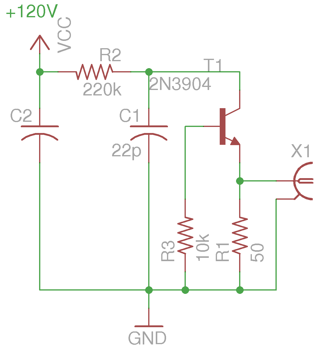
R2, C1 along with the NPN transistor form a relaxation oscillator. The capacitor gets charged via R2 and then rapidly dischargs when the collector-emitter voltage reaches the avalanche voltage. The discharge current flows through R1 during the avalanche and forms a fast-rise pulse between ground and the emitter. The choice of R2 and C1 is pretty liberal. In general, C1 can range from a few pF’s to tens of pF’s and R2 can range from 100K to 1M. The larger the value of C1, the wider the avalanche pulses due to increased discharging RC (R1C1) constant. But C1 cannot be too large as the energy released during the short avalanche period could cause the PN junction to fail. The RC constant (R2C1) determines the operation frequency. For the values given, the pulsing frequency is at roughly 30 kHz. R1 is chosen to match the characteristic impedance of the load. When used with an oscilloscope with 50 Ohm input, R1 should be 50 Ohm as well to avoid degradation of the output pulse waveform due to signal reflection.
R3 biases the collector-base junction. And according to the avalanche characteristics curve, it should be chosen small enough to allow a strong avalanche pulse. When experimenting with different transistors, R3 can be replaced with a 20K potentiometer and the optimal operating point can be adjusted empirically. Filter capacitor C2 (100nF is usually sufficient) is optional, depending on the stability and the ripple characteristics of the power supply.
If you are interested in the detailed operating principal of an avalanche pulse generator, you can take a look at this paper.
The majority of avalanche pulse generators hobbyists built used 2N2369, the same transistor used in Jim Williams’ original experiment. One of the main benefits of using 2N2369 is that it can avalanche at a relatively low voltage (under 90V). But most general purpose NPN transistors such as 2N3904, 2N2222, SS9013, etc. can be used in avalanche mode as well. Andrew Holme for example, had built such a pulser using the popular 2N3904. I have also found 2N3904 to be a great alternative to the hard-to-find 2N2369, despite having a slightly higher avalanche voltage threshold. During my build process, I sampled a large batch of 2N3904’s, and found that most can avalanche pretty consistently at around 100V.
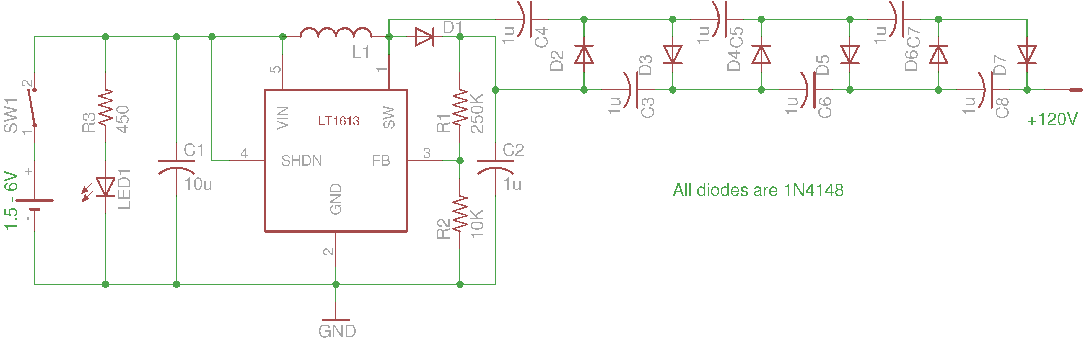
To generate the high voltage needed by the avalanche pulse generator, I used an LT1613 DC-DC converter chip. The output voltage (determined by 1.23*(1 + R1/R2)) is then quadrupled to just above 120V. The performance of LT1613 is comparable to the DC-DC converter Jim used (LT1073). Like LT1073, LT1613 can also be operated at a very low voltage, using a single 1.5V battery. Note that in Jim’s original HV circuit with LT1073, the feedback resistor was located at the HV output of the voltage multiplier, whereas in my circuit I left the feedback point at the primary output and leaving the multiplier voltage unregulated. The reason for this decision is that should R2 become unconnected the voltage input to the feedback pin will remain be within tolerance, avoiding any possible damage to the chip. Also, since the current requirement for the avalanche pulse generator is very low, regulating the HV output is not strictly necessary.
Below is a picture of the HV DC-DC converter built on a proto-board. In my particular build, I used a 4.5V battery holder which fits nicely behind the board. As I mentioned earlier, LT1073 can operate over a large voltage range and you could use a single 1.5V battery as well.
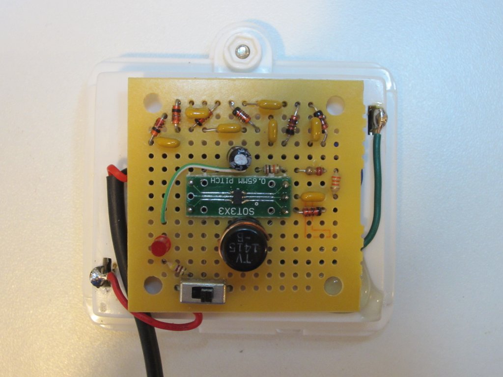
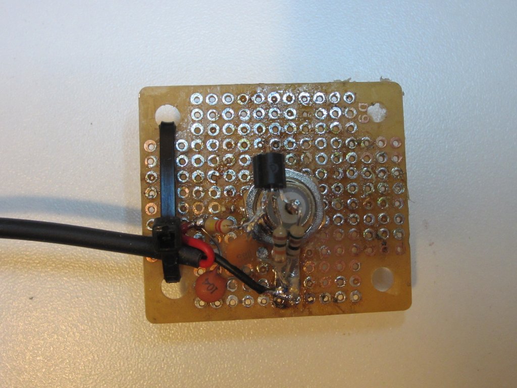
Here are a couple of pictures of the avalanche pulse generator board:
 |
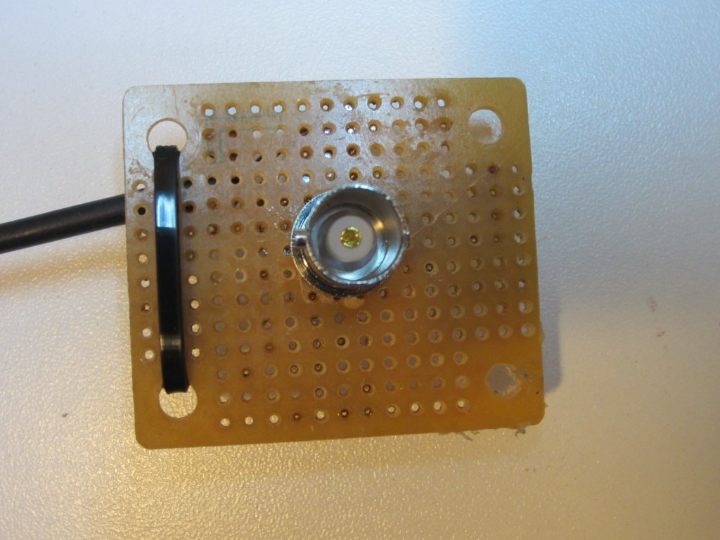 |
To keep the stray capacitance/inductance as low as possible, leads were kept short and components were placed as close to the BNC socket as possible. The layout of the components has a direct impact on the rise time of the generated pulses. In an earlier experiment while I was testing out the avalanche voltages of various transistors, I used a less strict layout and there was an observable reduction in the measured rise time (up to 100 pS).
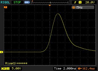
Here is an oscilloscope capture of the generated pulse on a Rigol 1102E (100MHz bandwidth) and the measured rise time is roughly 2.5ns, which translates into a bandwidth of roughly 140MHz (BW=0.35/Tr). Ideally speaking, the scope’s input impedance should be adjusted to 50 Ohm to match that of the pulse generator. Since Rigol 1102E does not have a 50 Ohm input option and I did not have a 50 Ohm feed-through terminator at hand the pulse was fed into the oscilloscope input directly. The resulted ringing due to signal reflection was manifested as a much slower falling edge.
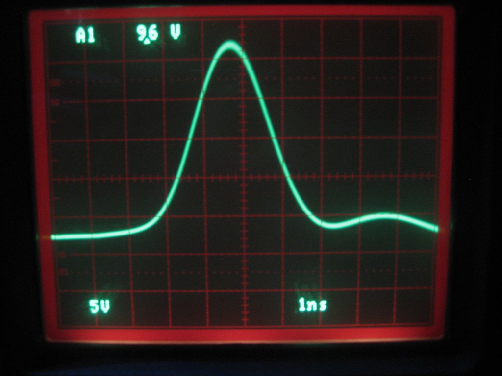
The following picture shows the same pulse observed on a Tektronix 2445 (150MHz bandwidth) with matching input impedance. The measured rise time is around 1.5 ns which corresponds to a bandwidth of approximately 230 Mhz. As you can see, the pulse has a sharper falling edge compared to the previous scope capture due to the matched impedance.
Using a fast-rising pulse to measure rise-time tends to give overly optimistic rise-time estimates as the pulse may not have reached its peak before falling off due to the short pulse width and the limited bandwidth of the instrument under test. More accurate measurements can be achieved by using a coaxial delay line or a pulse shaping network to widen the peek of the pulse.

