After I completed the filament driver and the circuit to drive the multiplexed VFD segments, it is time to finish the VFD clock project I had in mind earlier.
On the circuit side, there isn’t too much to it. All I needed was a realtime clock and a microcontroller to interface with the RTC and the VFD driving circuit I discussed before. The RTC chip I used is a high accuracy DS3232 from Maxim. A more popular RTC chip such as DS1307 can also be used here without too much programming change. The microcontroller I used is an Arduino bootloaded ATmega328P. Since the VFD driver circuitry requires a higher DC voltage (e.g. 27V, a few milliamps) for the anode plates and gates but the TTL circuit only needs 5V, the power supply must be able to provide both required voltages.
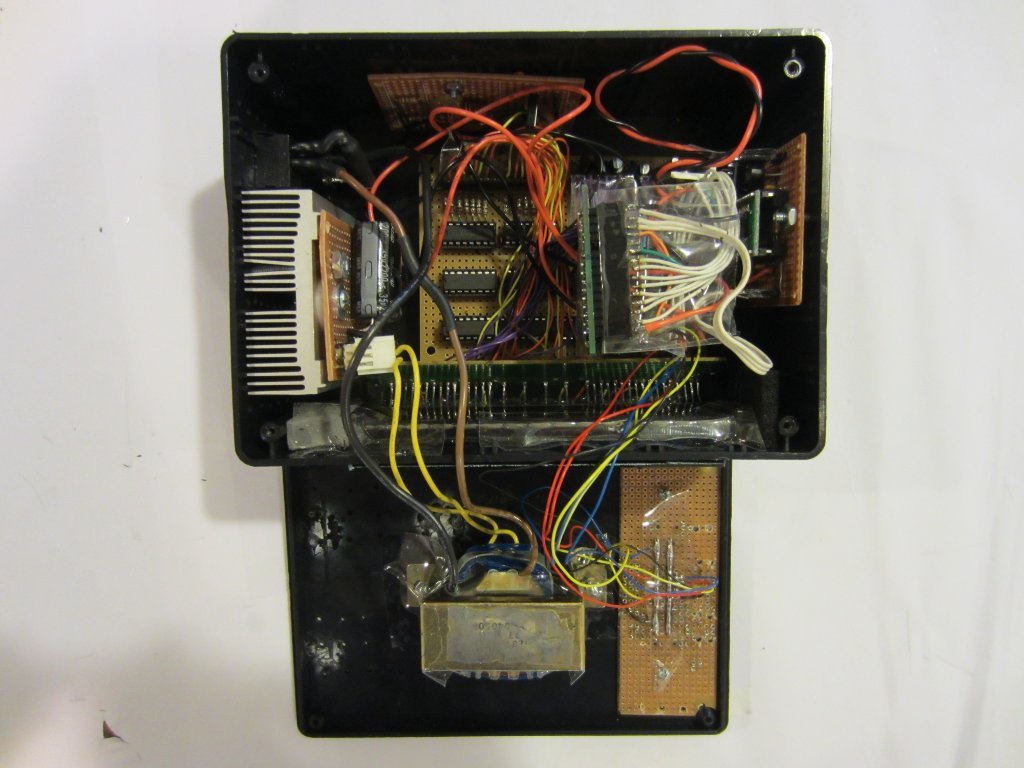
My original plan was to use a 20V transformer and then use the rectified and filtered DC output to drive the VFD plates/gates and then use a switching DC-DC converter chip to provide the 5V required by the rest of the circuit. But my order was delayed so I decided to go with a 7805 linear regulator I had on hand instead. Even though the current requirement for the 5V rail is low (at only around 150mA), the power dissipation for the 7805 is quite significant due to large differential between the input voltage and the output voltage. I had to use a rather beefy heat sink to keep the temperature under control (see picture below). Once my order arrives, I plan to replace this linear regulator with a switching regulator.
Here is a short video showing the basic functionality of this VFD clock I built. You can download the code towards the end.
|
View on YouTube in a new window |
Download source code: VFDClock.tar.gz

