Getting a rough measurement of the transistor hFE’s is useful when designing analog circuits. Unfortunately, only the lower end DMMs nowadays offer such functionality as it is becoming less and less useful to measure transistor hFEs in a world that is dominated by digital circuitry. Also hFE varies in different biasing situations and the hFE measurements on these cheap DMMs are typically done with a fixed base current (approximately 10 µA) in DC mode. But even with these limitations, hFE measurements can still be quite useful.
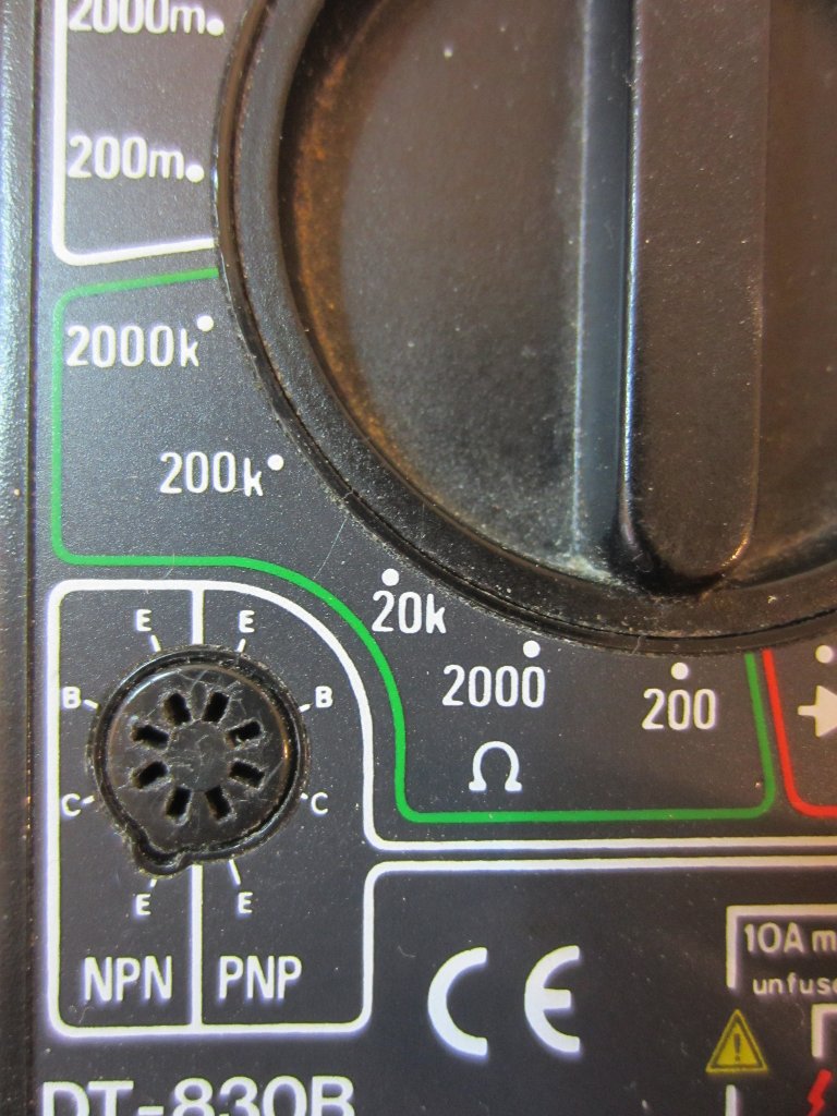
One of the biggest gripe I have over the hFE sockets on these cheap DMMs is that they are extremely difficult to use. They are mostly suited for transistors in TO-92 packaging. With some luck you can probably measure transistors in larger packages (e.g. TO-126). But if you are trying to measure hFEs for even larger transistors (e.g. in TO-220 or TO-247), you are out of luck.
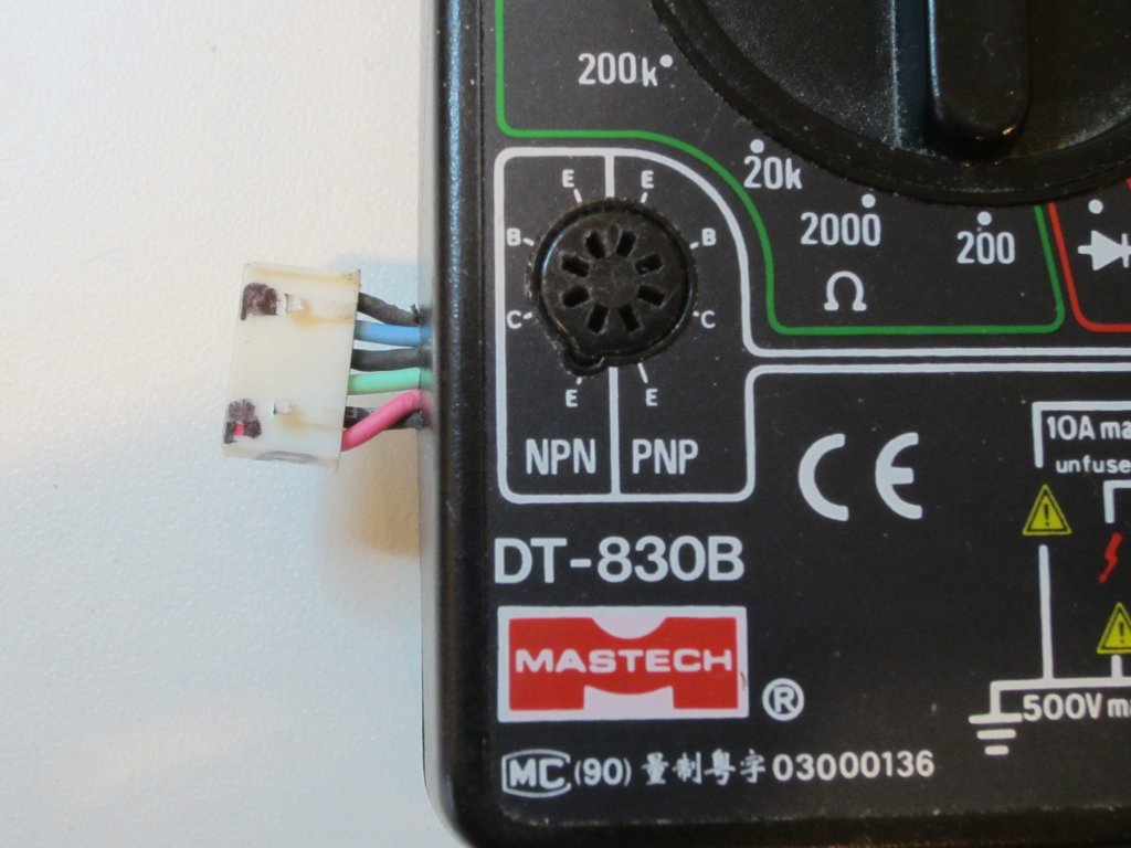
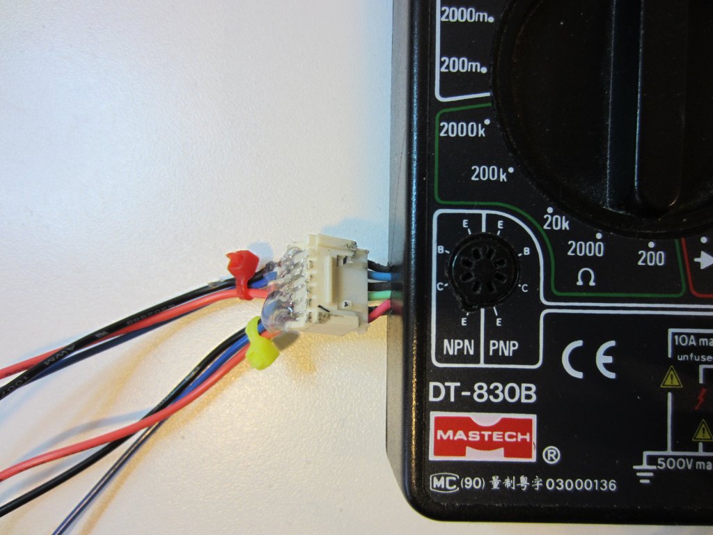
My solution here is to solder on an external socket so that I could attach mini-grabbers when I need to measure transistors that do not fit in the TO-92 socket. The picture below shows this approach. Basically, I just routed the EBC pins for both the NPN and PNP sides out to a 6-pin socket. The wires on the red zip tie side are for NPN transistors and the wires on the yellow zip tie side are for PNP transistors. To make these clips easily identifiable, I also color coded the wires and clips: black for emitter, blue for base and red for collector. Alternatively, you could just use one set of clips and use a 3PDT switch to switch between NPN and PNP measurements.
|
|
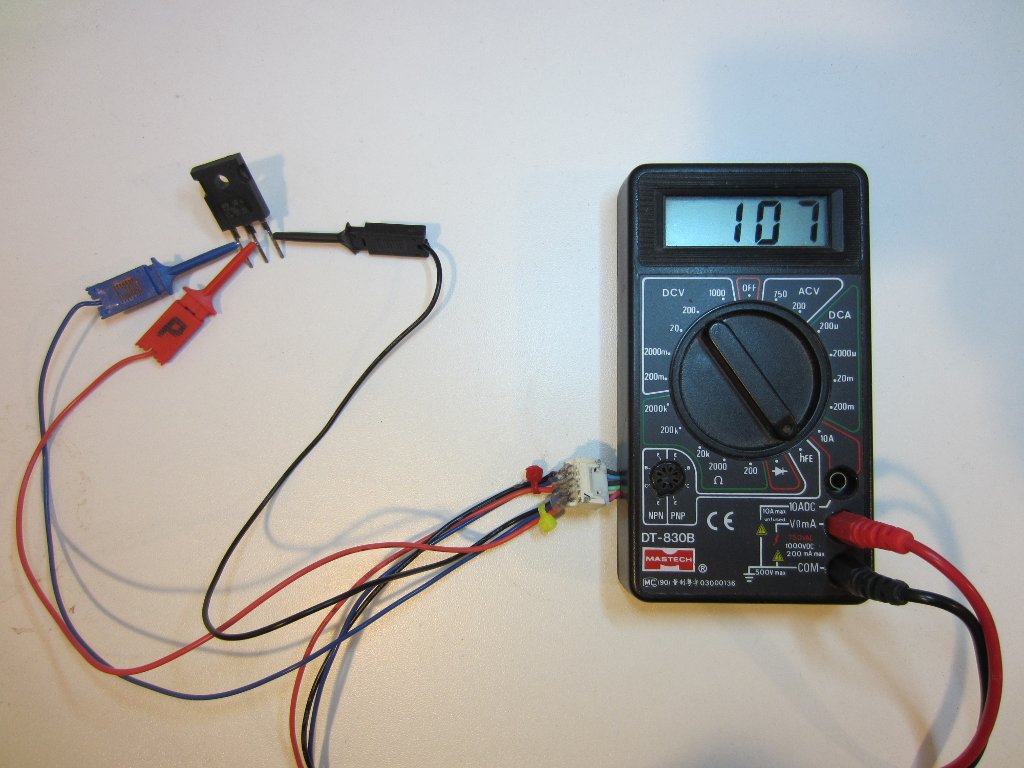
Here is a picture showing the hFE measurement of a TIP36C transistor (PNP):
By the way, while the accuracy of these cheap DMMs are questionable, they can be easily calibrated (with a cheap voltage source, for instance). And after calibration, they actually perform reasonably well.

