Here is a teardown you do not see very often. I recently bought an HP 5350B 20 GHz microwave counter off eBay. HP 5350B uses harmonic heterodyne down-conversion technique to convert the microwave frequency into the range of its internal low frequency counter. It can measure frequencies from 10 Hz all the way up to 20 GHz via two separate inputs.
The unit I got was made in 1989 and had the high stability oven option (option 001). Even though it passes all the self tests, the oven crystal oscillator does not seem to operate under the correct temperature as the OVEN indicator would remain on after a prolonged period of time (in normal circumstances, preheating the oven takes less than 10 minutes and the indicator should be off once the oven has reached the operating temperature). I will do a separate post on trouble-shooting the oven controlled oscillator and concentrate on the teardown in this post.
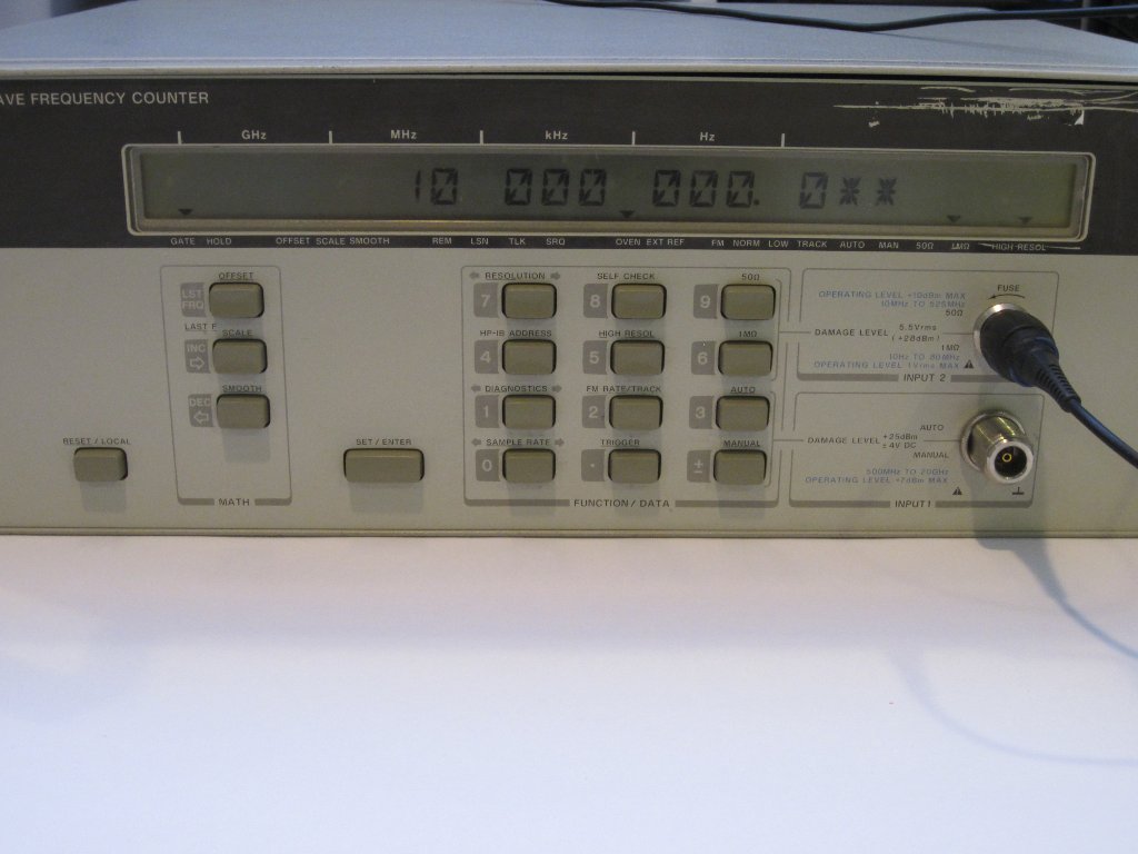 10 MHz signal from the timebase, high res mode |
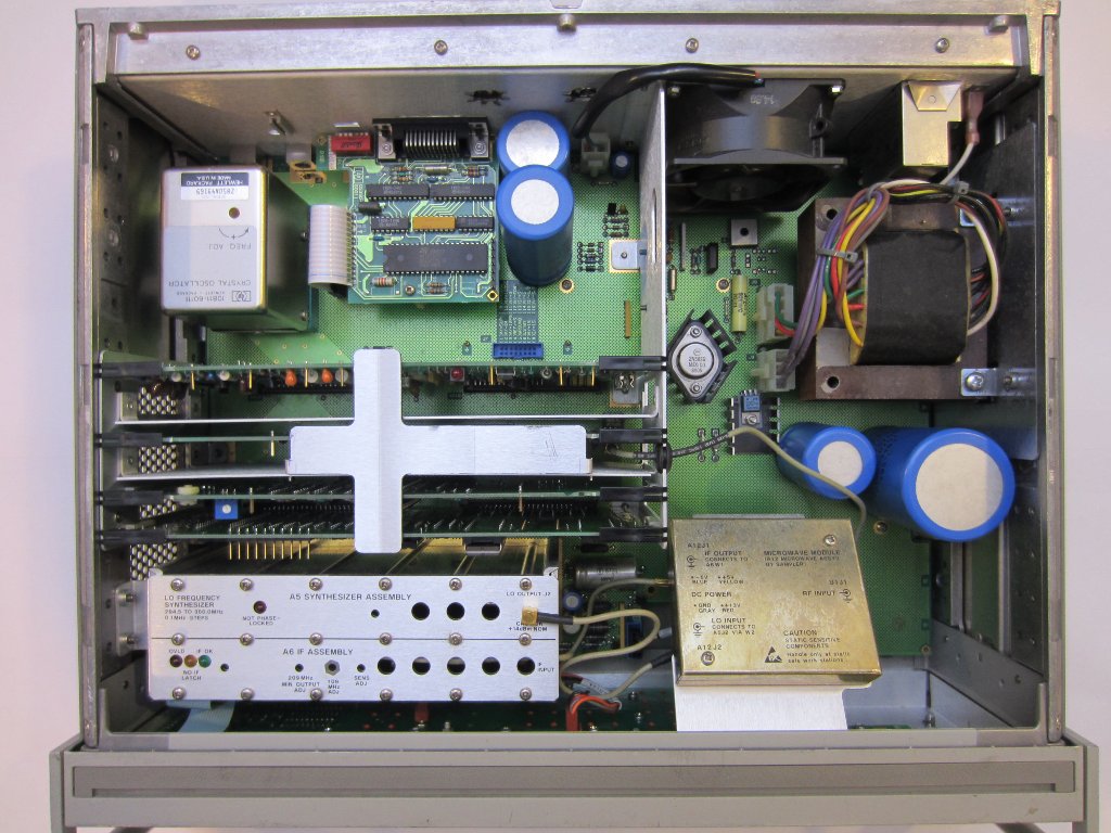 top panel removed |
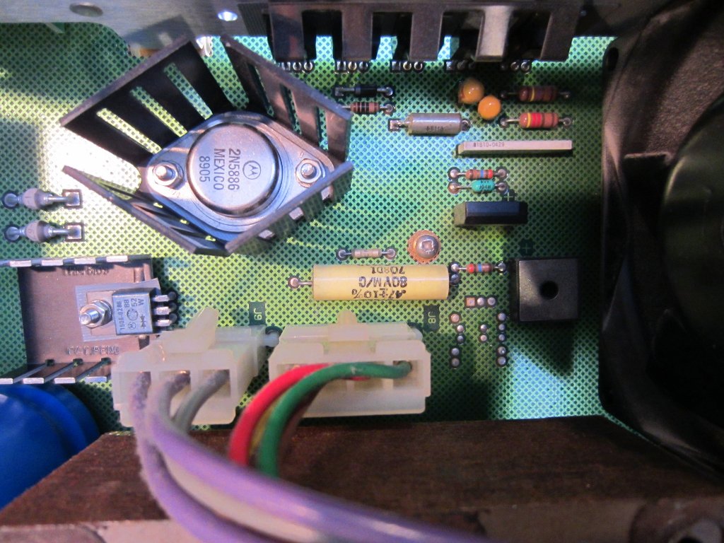 Power supply circuitry |
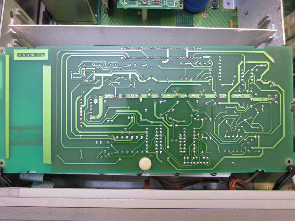
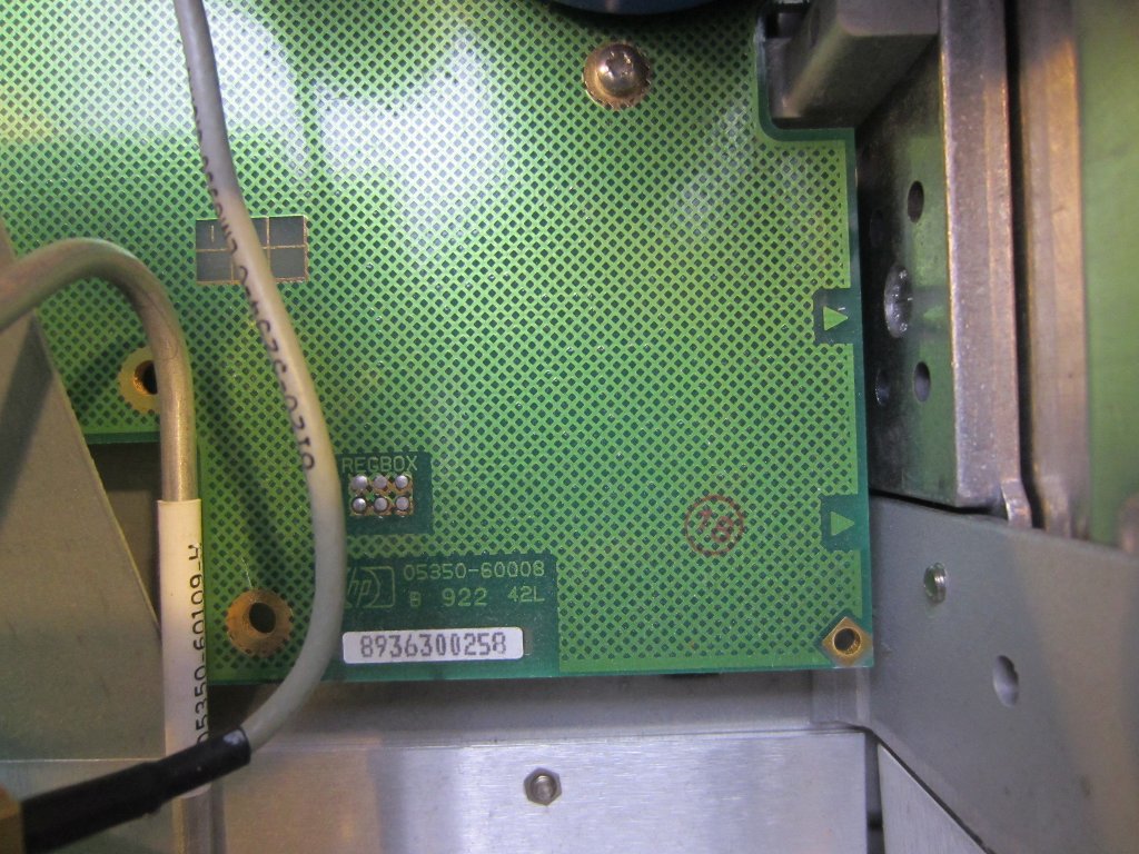 Etched ground pattern |
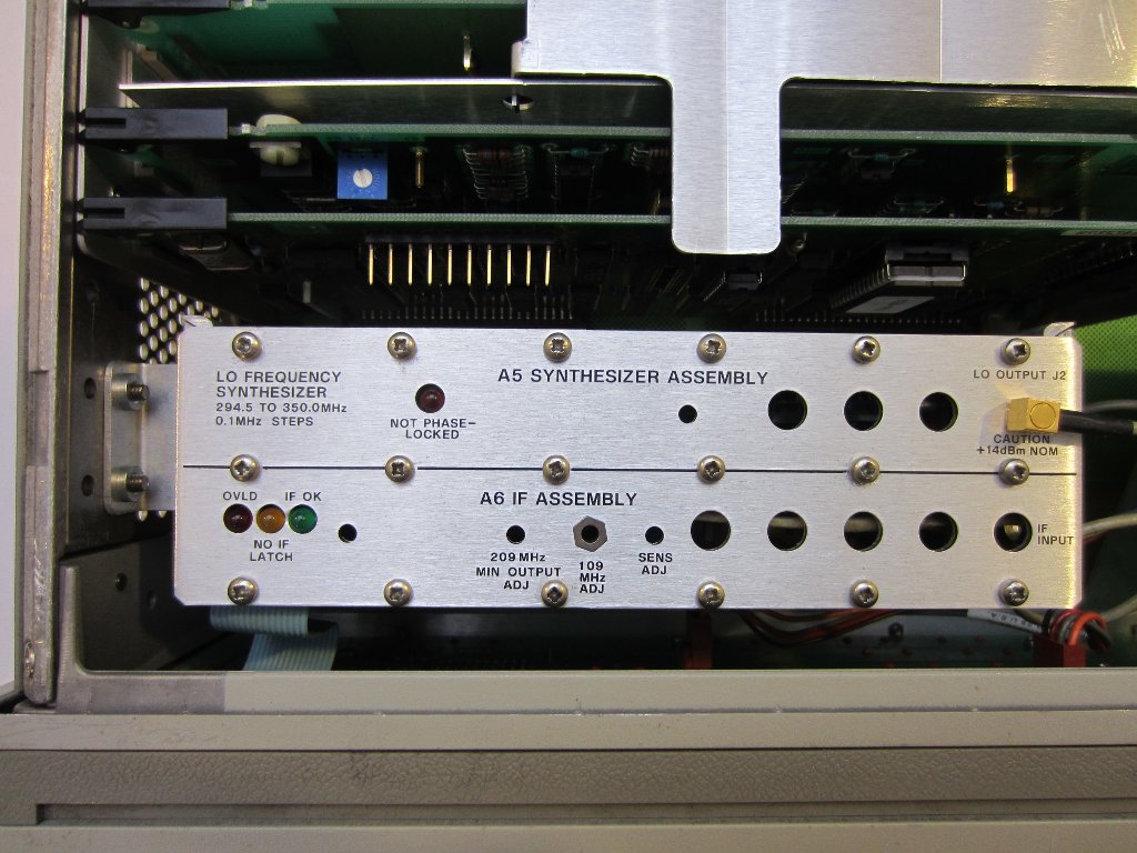
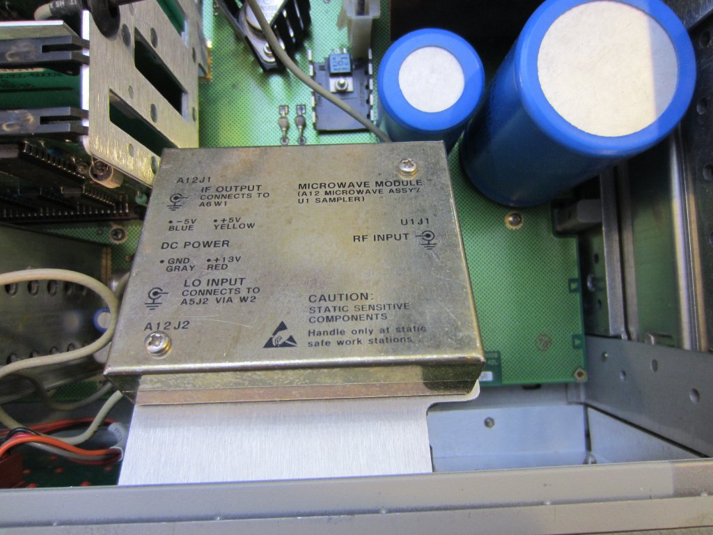
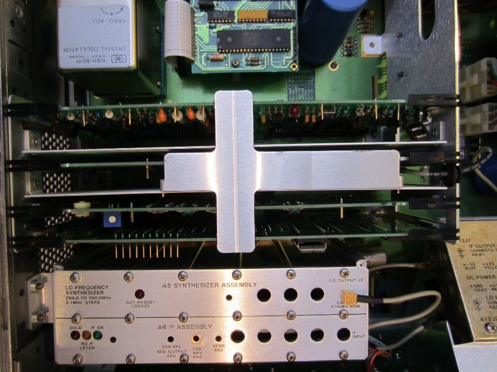
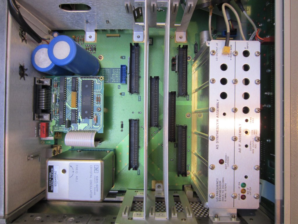
The A5 (sythesizer) and A6 (IF amplifier/detector) assemblies are shielded under a thick aluminum can. And the microwave module and sampler (A12) is in another metal can mounted on an angle.
|
|
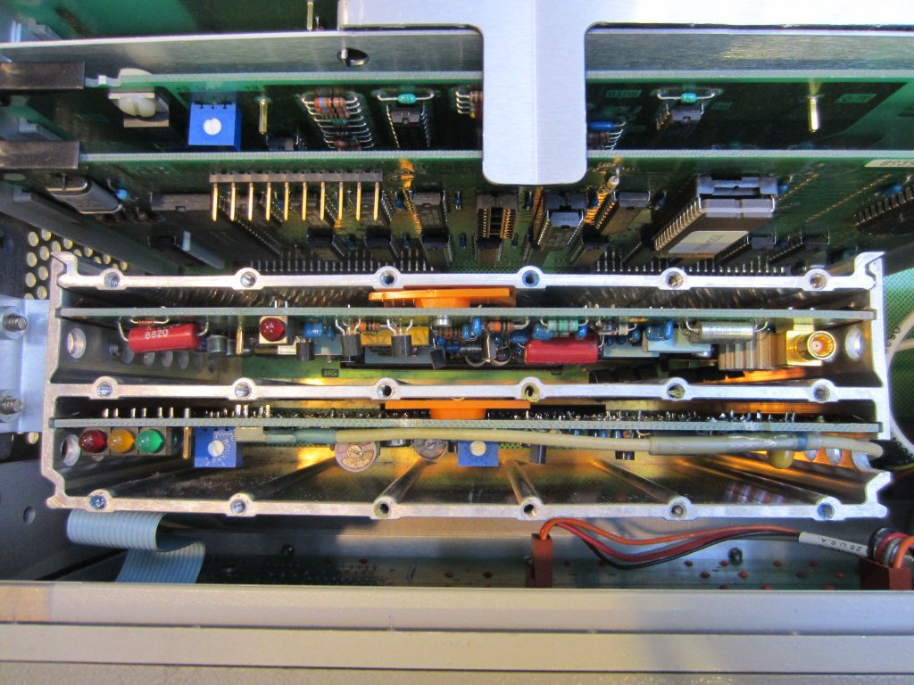
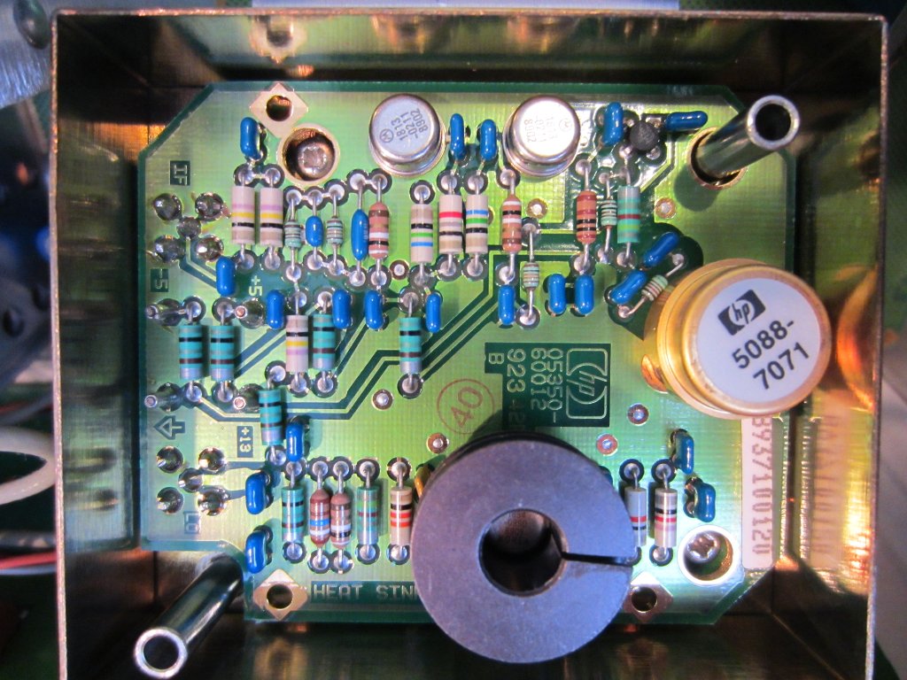
The picture to the left below are the A5/A6 boards with the top shielding cover removed. And the picture to the right is the microwave module/sampler (A12) with the cover removed. The larger gold colored metal can (HP 5088-7071) is the GaAs sampler.
|
|
| [adsense] |
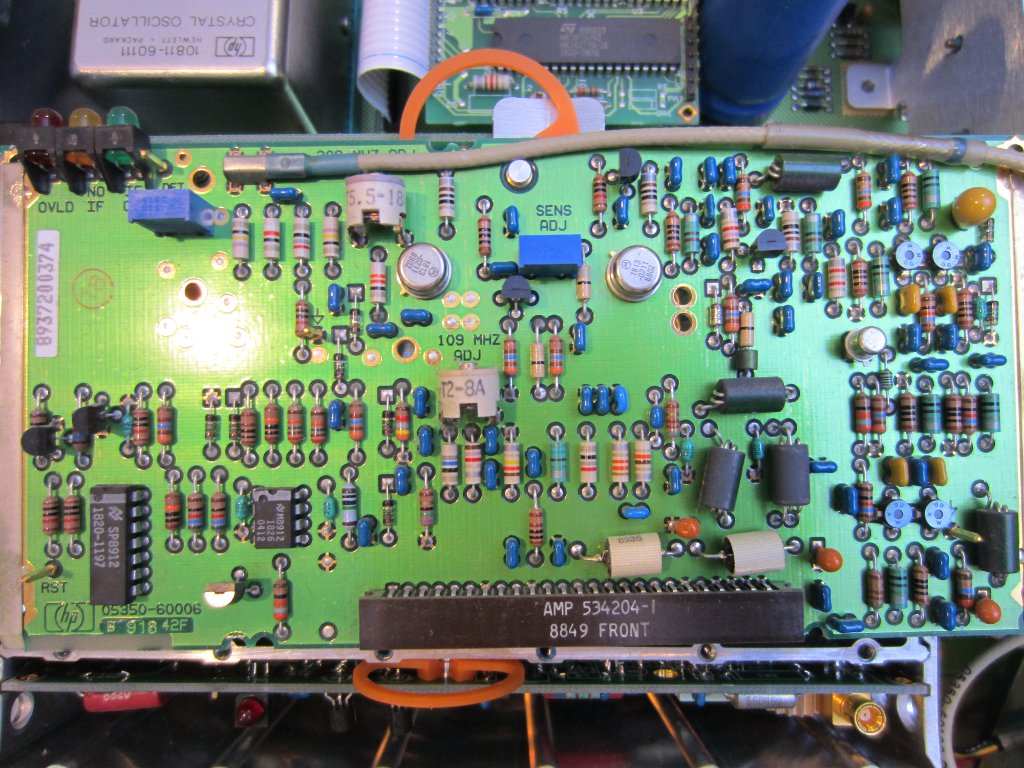
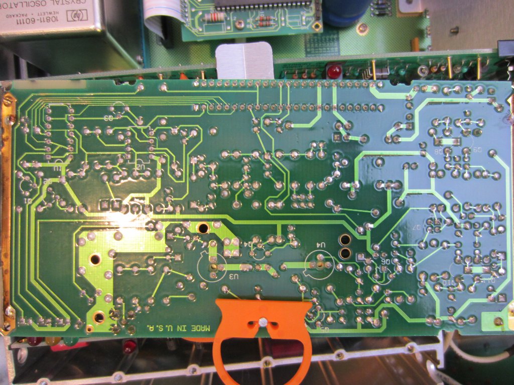
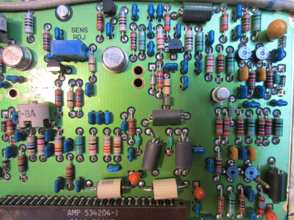
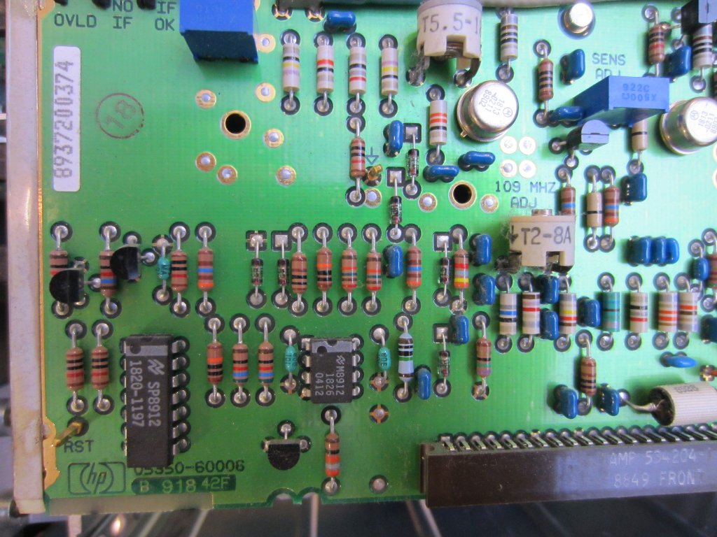
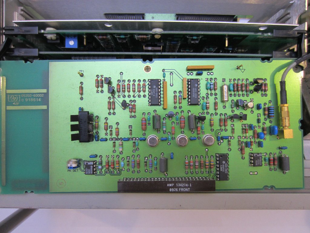
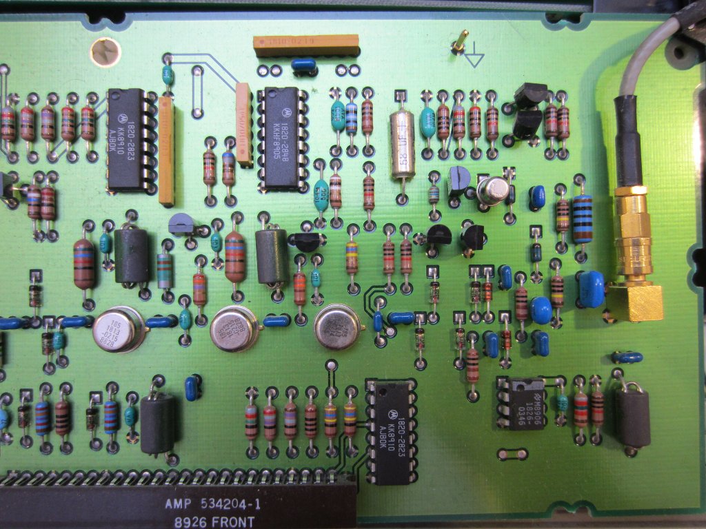
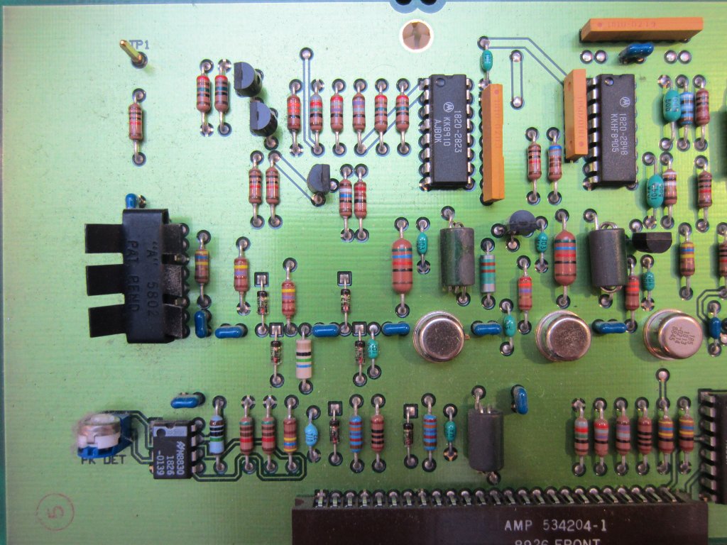
The following four pictures are the A6 IF amplifier/detector board.
|
|
|
|
The next four pictures are the A5 synthesizer board.
|
|
|
 |
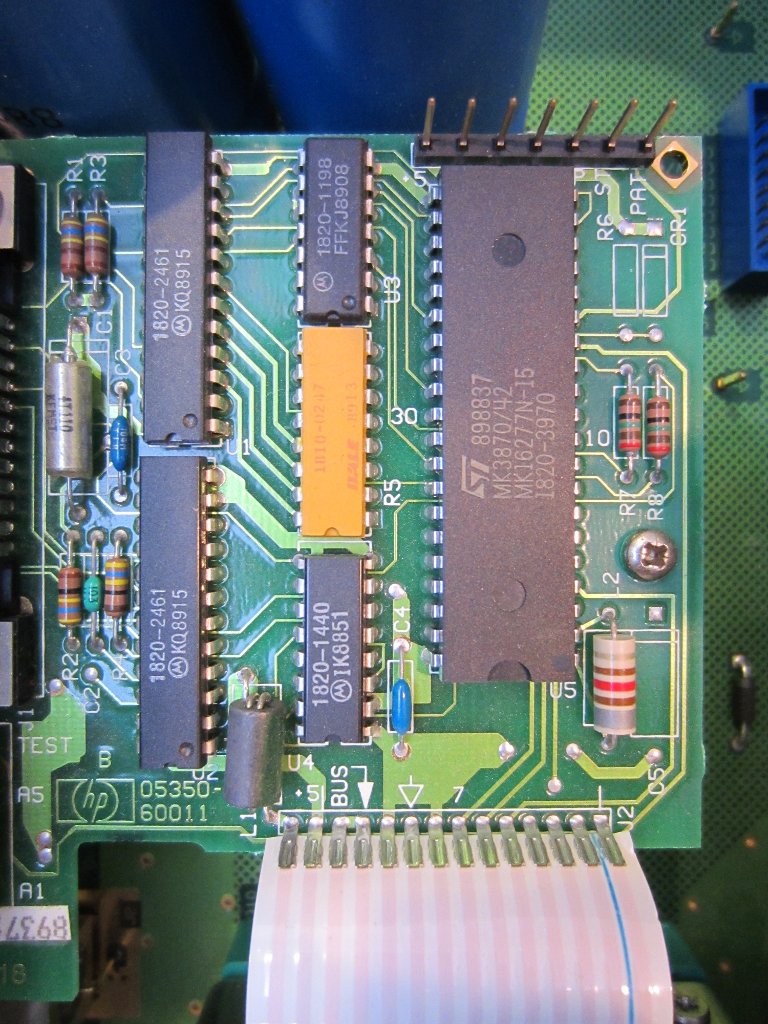
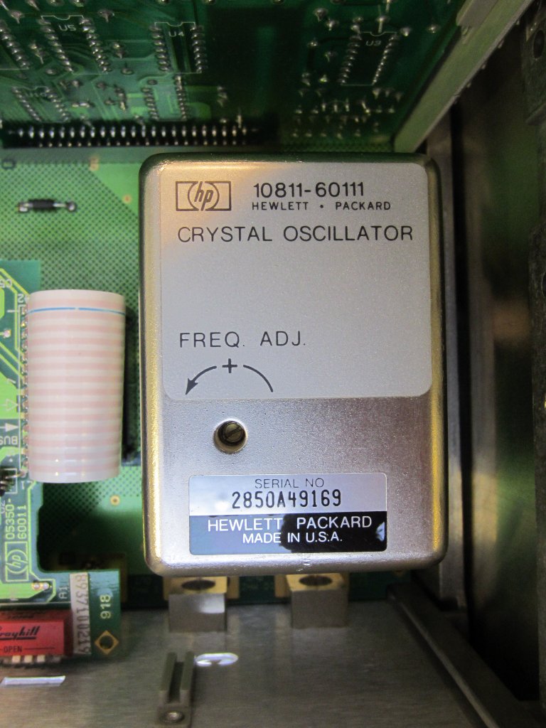
The GPIB controller board is mounted on a standoff above the motherboard. And the picture on the right is the oven controlled crystal oscillator (OCXO).
|
|
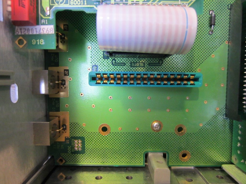
The picture on the left below shows the socket where the OCXO sits. The OCXO is also secured via two screws from the bottom of the PCB. The picture on the right shows A1-A4 plugged onto the mainboard, there is a tension clip on the top to further secure these plugins.
|
|
| [adsense] |
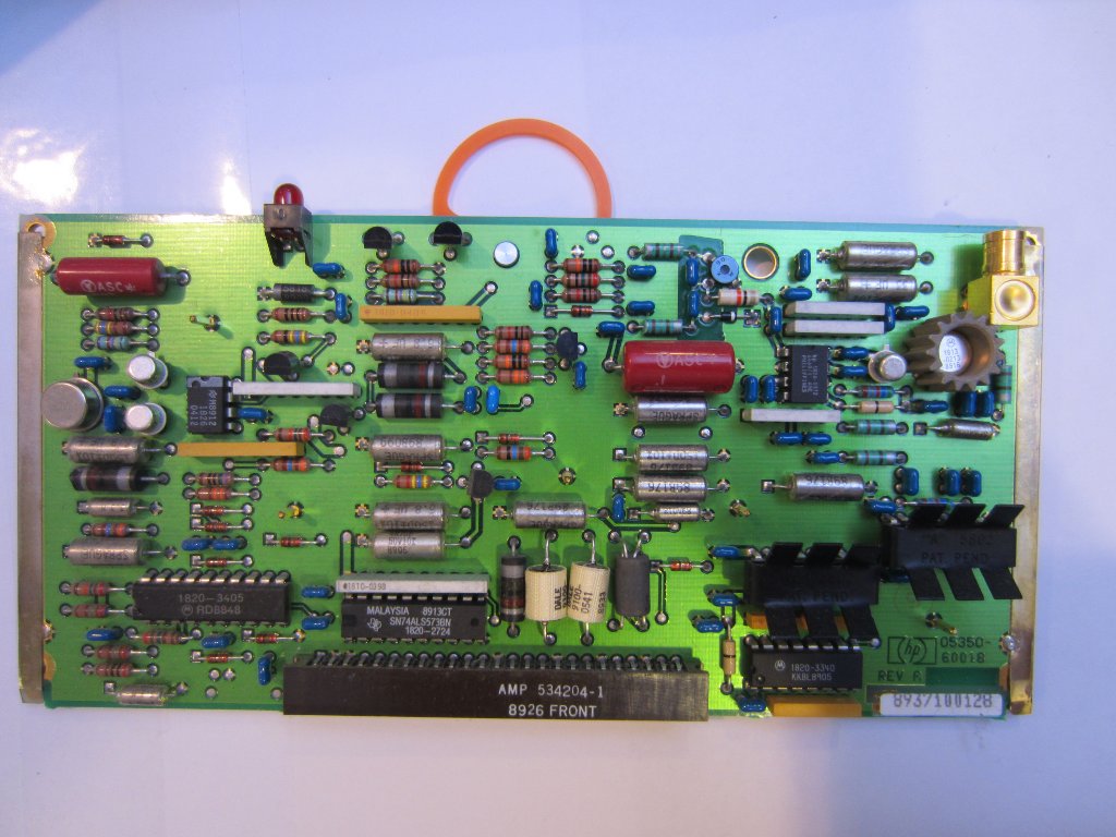
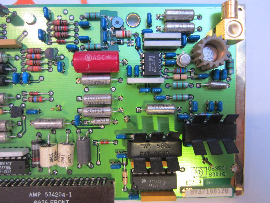
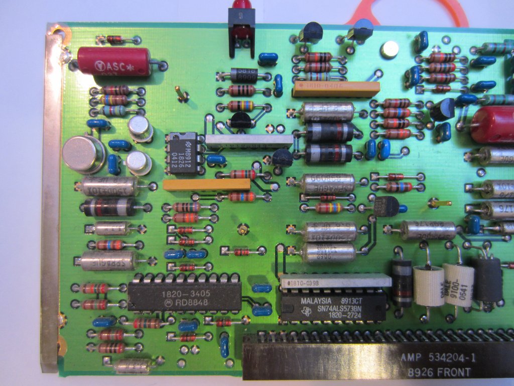
Here are some pictures for the A1 (timebase buffer/power supply control), A2 (low frequency input), A3 (counter) and A4 (microprocessor) boards. The fuse holder on A1 is reserved for an optional 5000 hours elapsed time indicator.
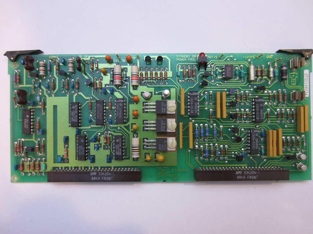 A1 |
 A1 |
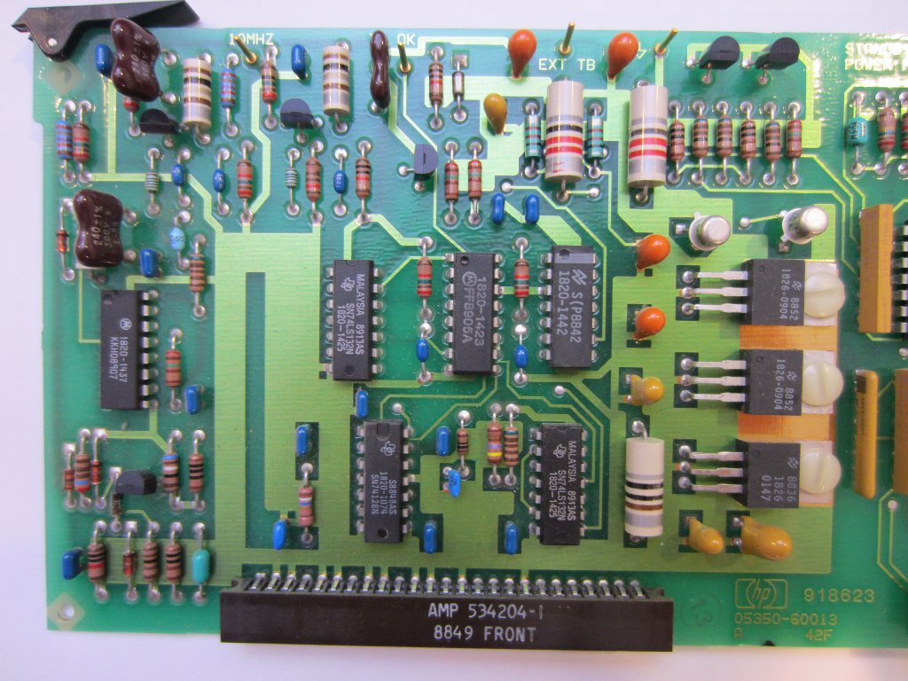 A1 |
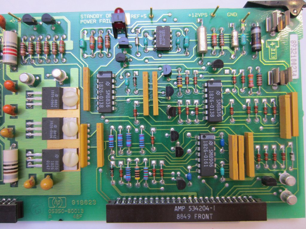 A1 |
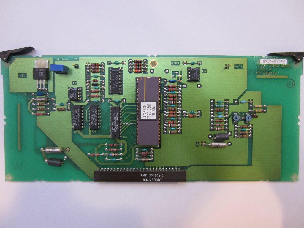
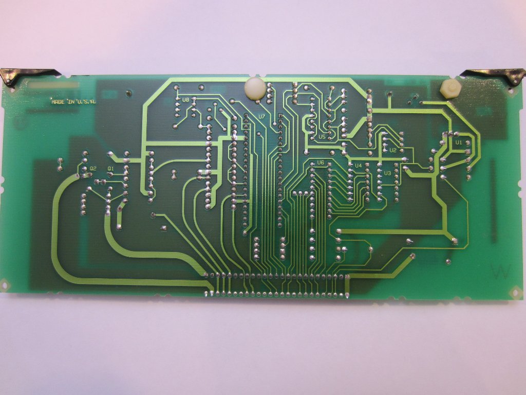
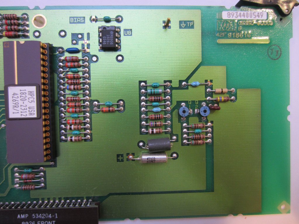
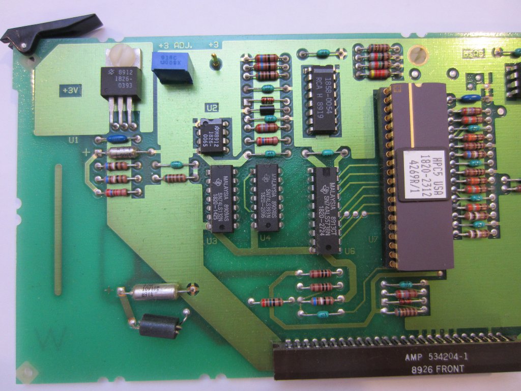
 A2 Low Frequency Input |
 A2 Low Frequency Input |
 A2 Low Frequency Input |
 A2 Low Frequency Input |
 A3 Counter |
 A3 Counter |
 A3 Counter |
 A3 Counter |
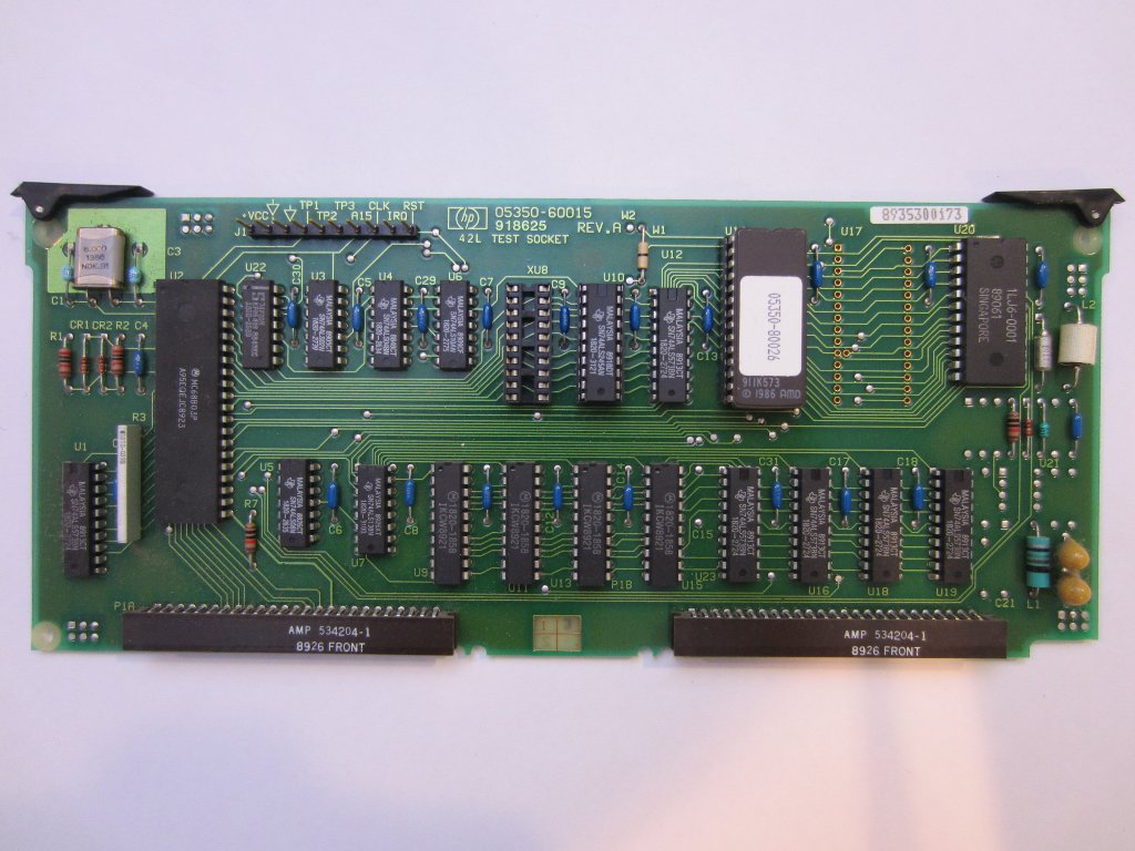 A4 Microprocessor |
 A4 Microprocessor |
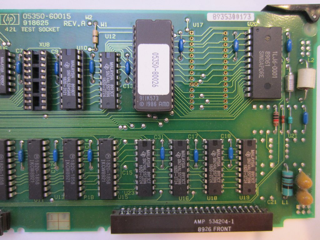 A4 Microprocessor |
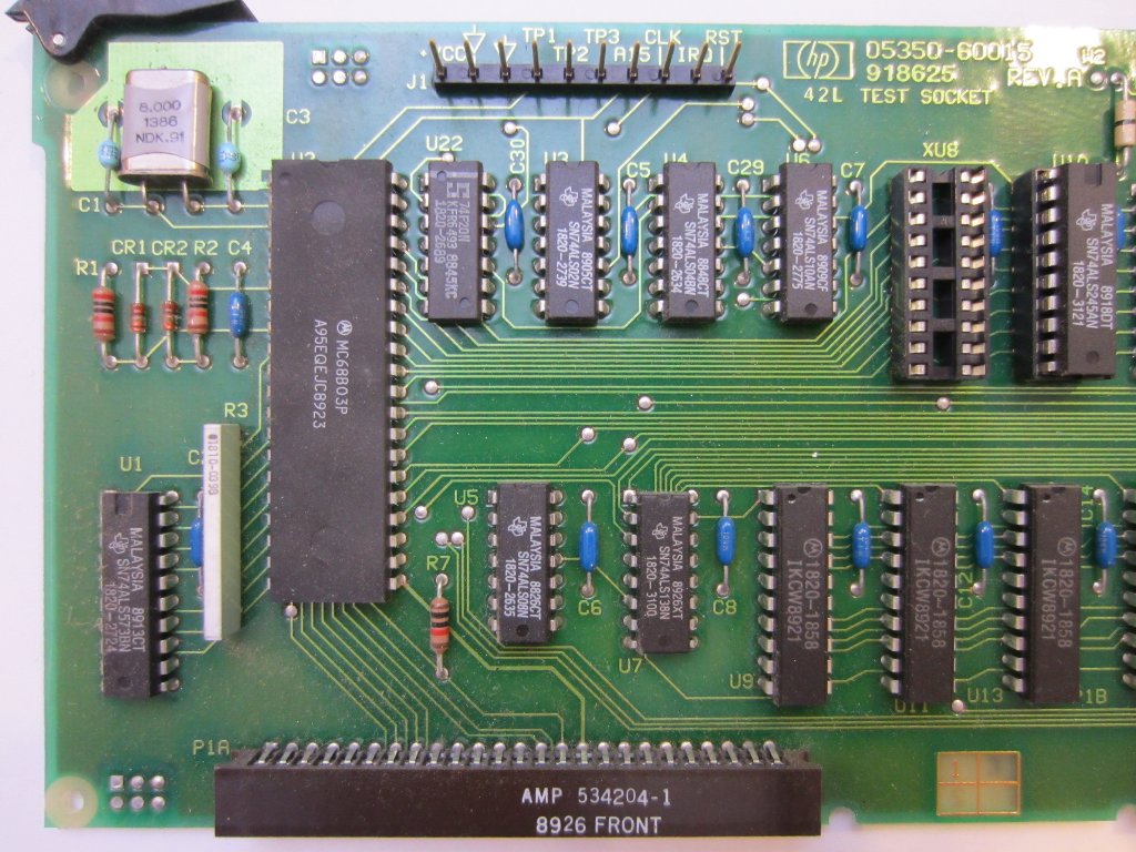 A4 Microprocessor |
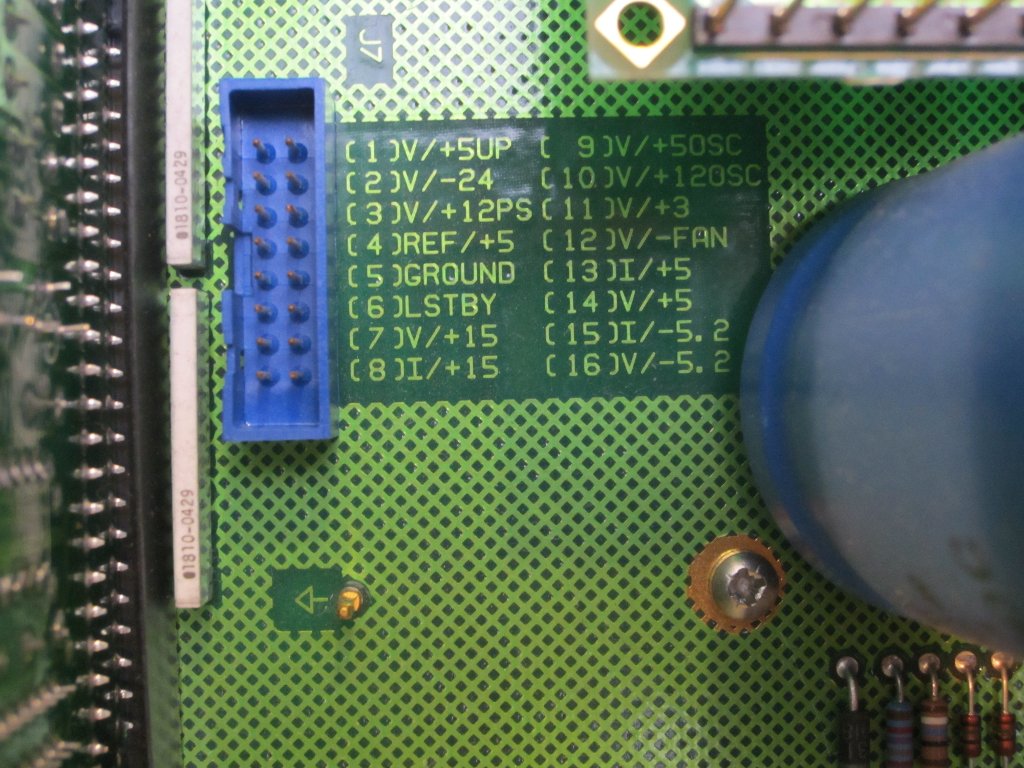
The picture on the left below shows the motherboard with A1-A4 boards removed. The socket shown in the picture on the right can be used to conveniently check various board voltages.
|
|
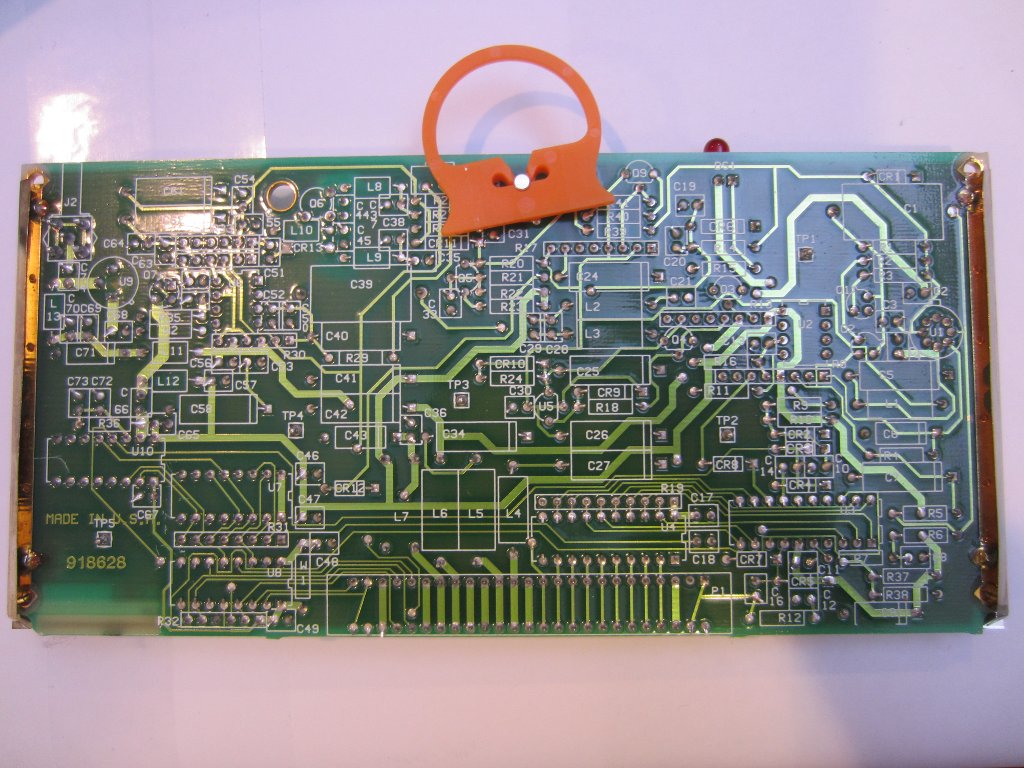
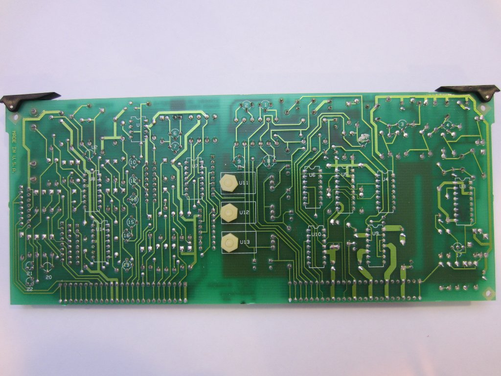
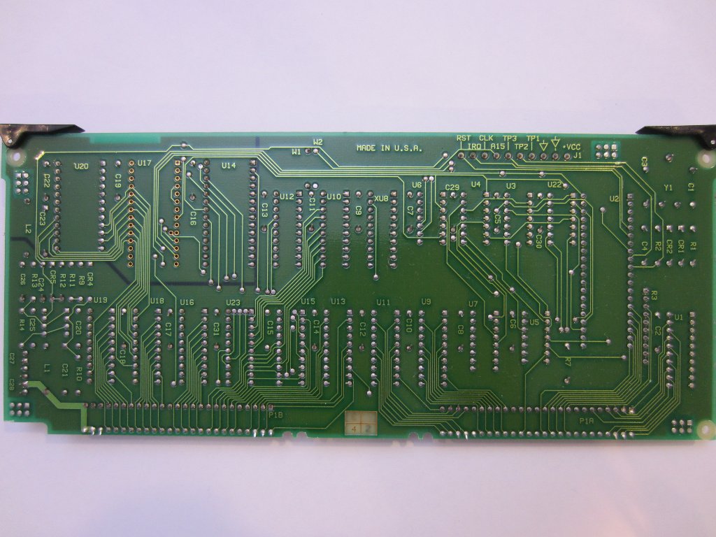
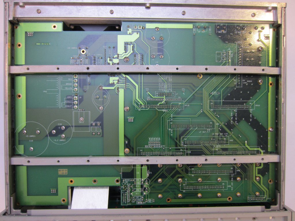
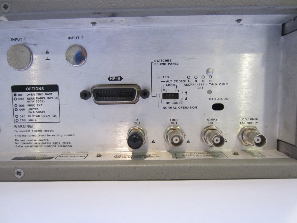
Here is a picture of the flip side of the PCB. All the components and test points are clearly marked. And finally, here is a picture of the back of the instrument.
|
|
As mentioned earlier, I will take a look at the OCXO in my next post. Stay tuned.

