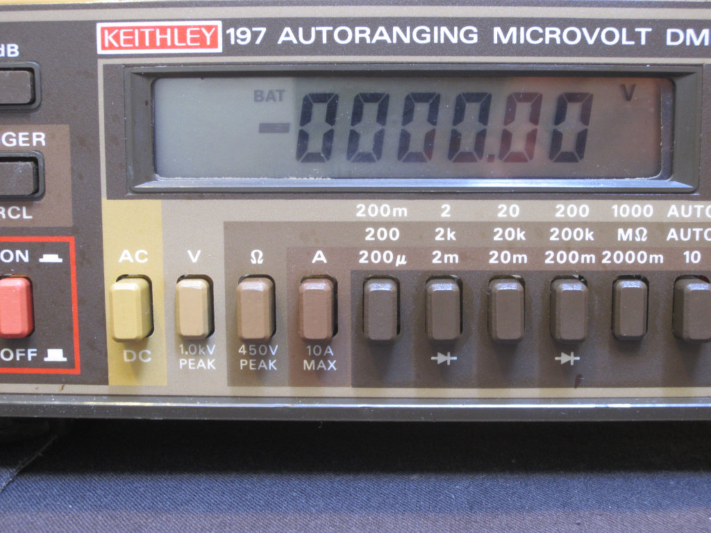
I have been quite happy with my fixed-up Keithley 197 5 ½ digit bench meter purchased from eBay (you can find the teardown pictures here) earlier this year. Keithley 197 has a battery pack option (Model 1978), and this option allows it to run on battery power for 5 hours without having to plug into the mains. While it is far from being a truly portable meter, its performance easily surpasses most hand-held multimeters. So I decided to build the battery option myself and hopefully I would be able to use the meter more often in places where power outlets are not available.
Fortunately, the service manual for Keithley 197 is widely available. Here is the schematics of the original design:
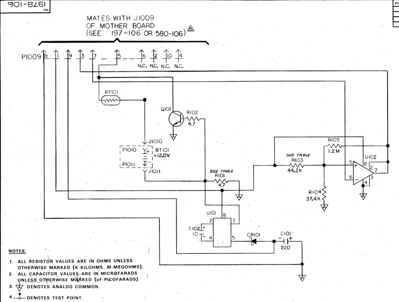
Basically, it uses a Maxim SI7661 (now obsolete) charge pump to create the symmetric negative operating voltage (-12V). And the charging circuit is formed simply with resistors (RT101 and R101 along with the 10 Ohm resistor R131 on the main circuit board) . These resistors in series limit the terminate charging current to around 30mA. Q101 is used to limit the maximum charging current through the battery during initial charge. As the charge current increases, the the voltage drop across R101 will increase accordingly. When the voltage drop exceeds 0.6 to 0.7 V (roughly 150mA), Q101 starts to conduct and shunts the excess charging current. When in battery operation mode, the B-E junction is reversely biased so Q101 is off and does not draw any current from the battery.
Because Keithley 197 relies on the regulated +10V and -9V for proper operation, the input voltage to the regulator cannot drop below certain level otherwise the circuit will loose regulation and cause the regulated output voltage to drop. This voltage drop will affect the accuracy of the conversion circuit, causing inaccurate measurement results. Thus a comparator is used to pull down pin 16 on the MCU (U114) when the battery voltage drops to around 11.6V and a low battery indicator (BAT) is then lit on the LCD.
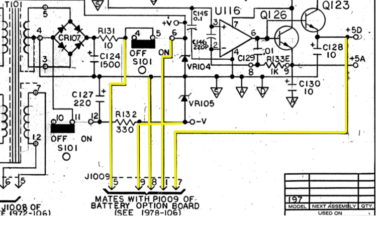
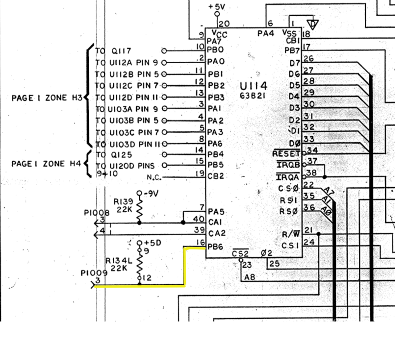
The schematics below illustrate where the signals from the battery board connector connect to the rest of the system.
|
|
While the charging circuitry is extremely simple, it has some obvious drawbacks. one problem is that when the battery is fully charged, there is still some significant amount of current flowing into the battery. So when the instrument is left plugged in for an extensive amount of time, the life of the battery pack could be shortened significantly due to excessive overcharging. One way to solve this problem is to increase the value of RT101, but because of its location increasing its value will cause additional voltage drop to the voltage going into the regulator.
So I modified the circuit a bit and came up with the following design:
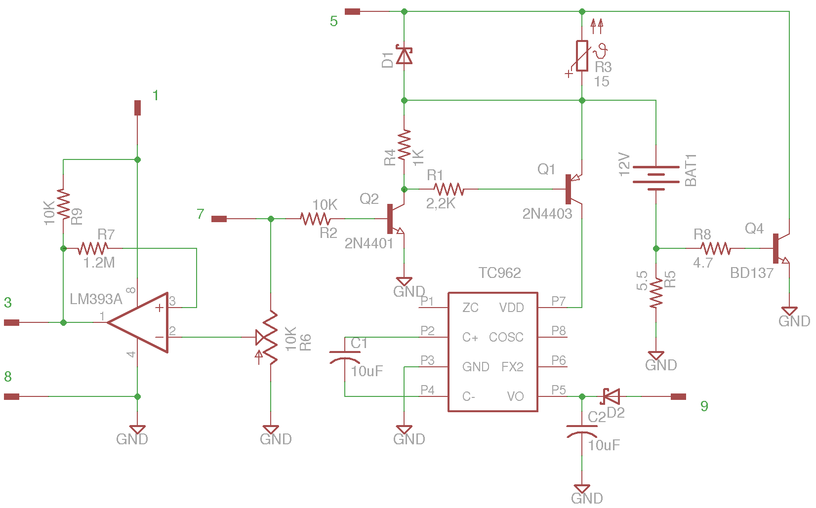
Since SI7661 is obsolete now, I replaced it with a Microchip TC962 high current charge pump DC-to-DC converter chip.
A ten-turn trim pot is used in place of R103 and R104 so that the trip voltage can be adjusted easily. RT101 is replaced with a Schottky diode in parallel with a low Curie temperature PTC thermistor. The thermistor is attached to the surface of the battery pack to monitor its temperature. When the battery is fully charged the surface temperature begins to rise, this will cause the resistance to increase and thus lower the trickle charging current. When in equilibrium the trickle charging current can be reduced to lower than 10mA (depending on the PTC used). To counter the effect of the PTC resistance during battery discharge, a Schottky diode is put in parallel so that the PTC is shunted when the instrument is running on battery.
I also added Q2 and Q1 to switch the charge pump on and off. In the original design the charge pump is connected to the “On” side of the power switch so that it only operates when the power is turned on. I could have used the same design here but with the introduction of Q1 and Q2, the charge pump can be turned on and off via a control signal (here I used the same 5V reference signal the comparator uses). With this design, we could use the other half of the comparator to detect whether we are running on mains power or on battery and turn on the charge pump only when we are on battery. For now, the charge pump operates whenever the meter is turned on (same as the original design) and D2 is used to ensure current does not feedback into the DC-DC converter when on mains power.
Note that the pullup resistor (R9) on the output of the comparator can be omitted as the MCU pin the output connects to already has a pullup resistor in place, I put it in the diagram as a reminder since LM393 is an open collector comparator.
The battery connector can be seen here in the picture below. Pin 1 is located on the upper right corner, and the remaining pins are numbered counterclockwise.
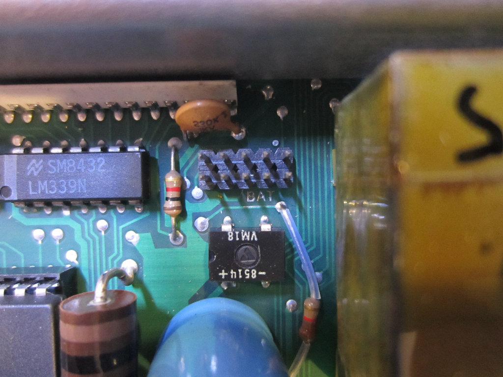
The pinout for the battery connector is as follows:
- Unregulated voltage input (“On” side of the power switch)
- N.C.
- Comparator output (to IC114 pin 16)
- N.C.
- Unregulated voltage input (“Off” side of the power switch)
- N.C.
- 5 V regulated output
- Ground
- Charge pump output
- N.C.
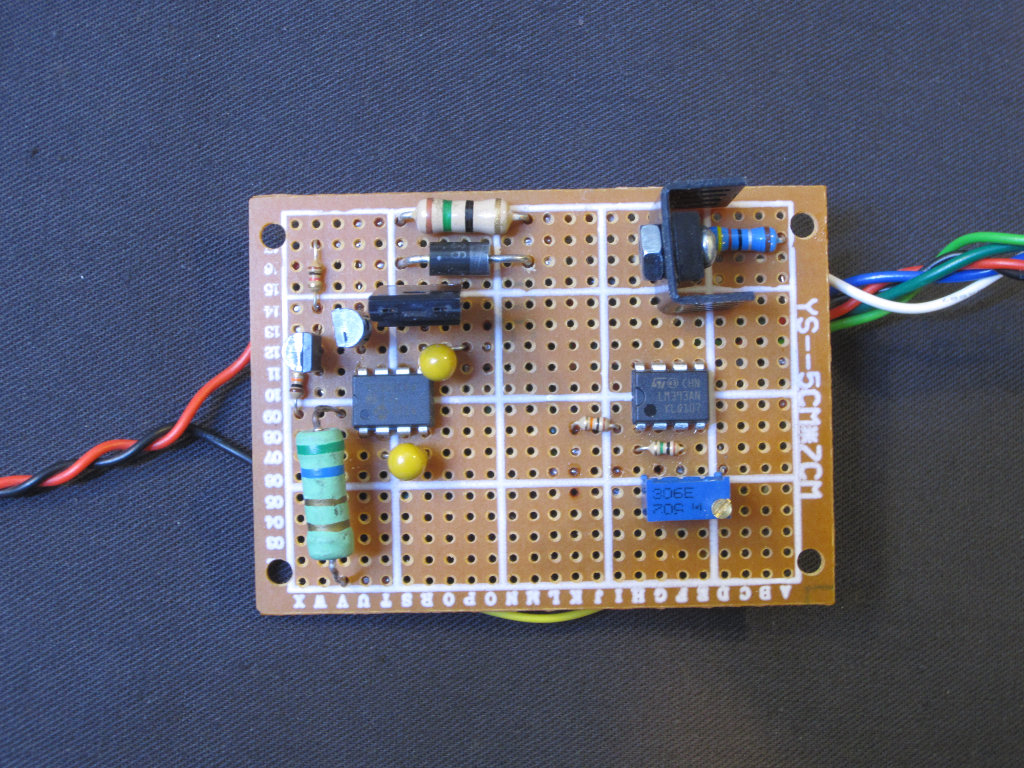
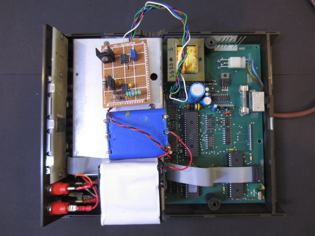
Here are a couple of pictures of the battery option board I built. I do not have a 12V rechargeable battery pack on hand at the moment, so I used two battery holders to form the 12V battery pack needed. It looks a bit messy but I will replace the batteries as soon as I get a proper battery pack.
|
|
The batteries I used are 2100 mAH NiMh ones, and during battery operation the current draw is at around 100mA so with this configuration the meter can be remain battery powered for around 20 hours.
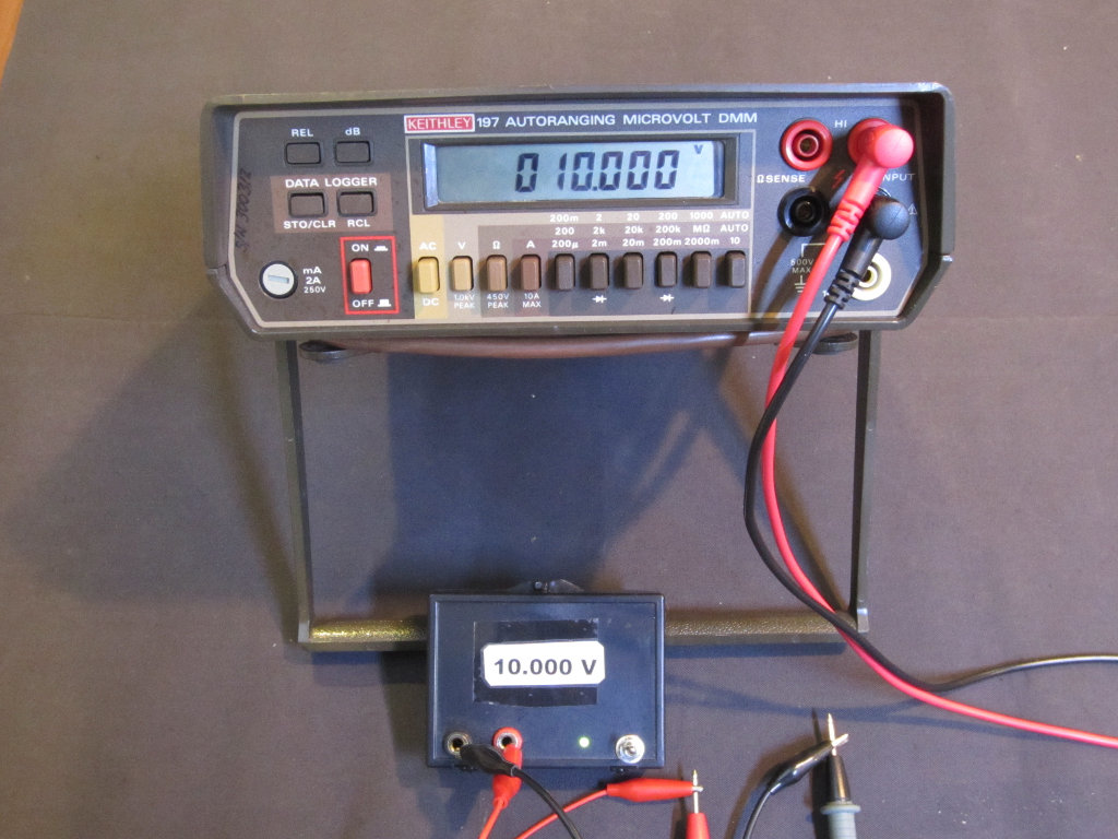
The picture on the left below shows the meter operating on battery measuring a 10V precision voltage reference I made. The voltage reference is calibrated against my Keithley 196. The picture on the right shows the low battery indicator when the battery voltage drops below 11.6V.
|
|

