I just picked up another high voltage power supply, this time it is a working Bertan/Spellman 225-20R 20kV one. Unlike the Bertan 205A-05R that I did a teardown with last time which was entirely analog, this one can be controlled digitally either via the front panel or via GPIB from the back. In this blog post, let me share some of the teardown pictures with you. If you are interesting in seeing some cool experiments with this high voltage power supply, you can scroll down and watch my video towards the end.
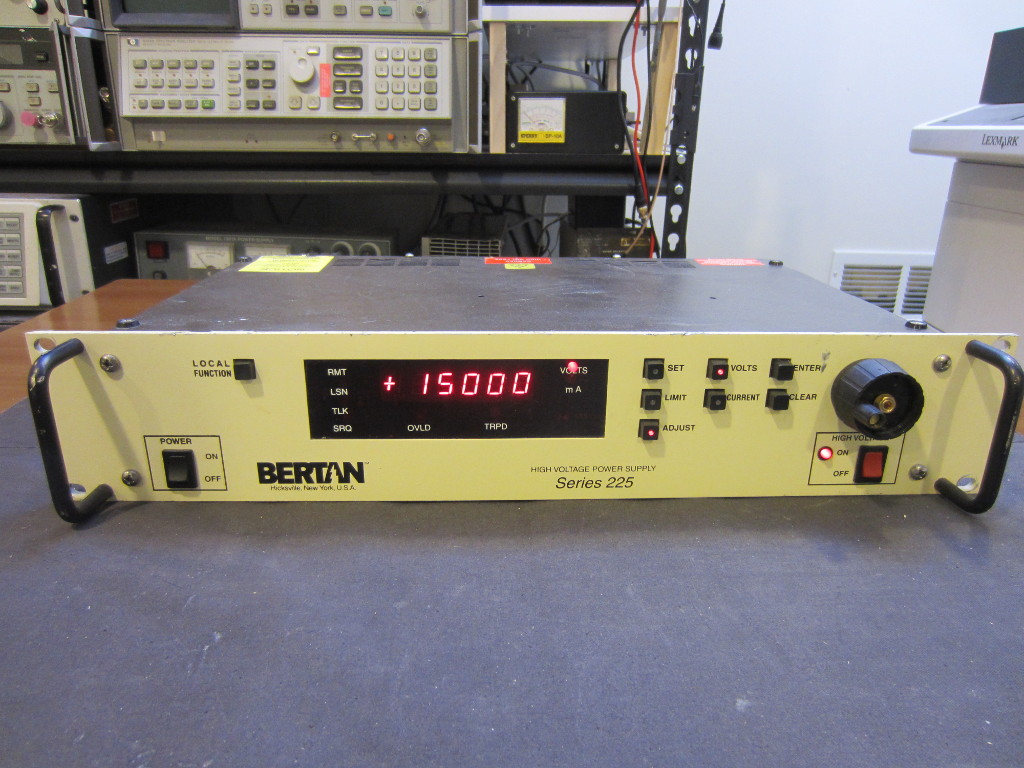
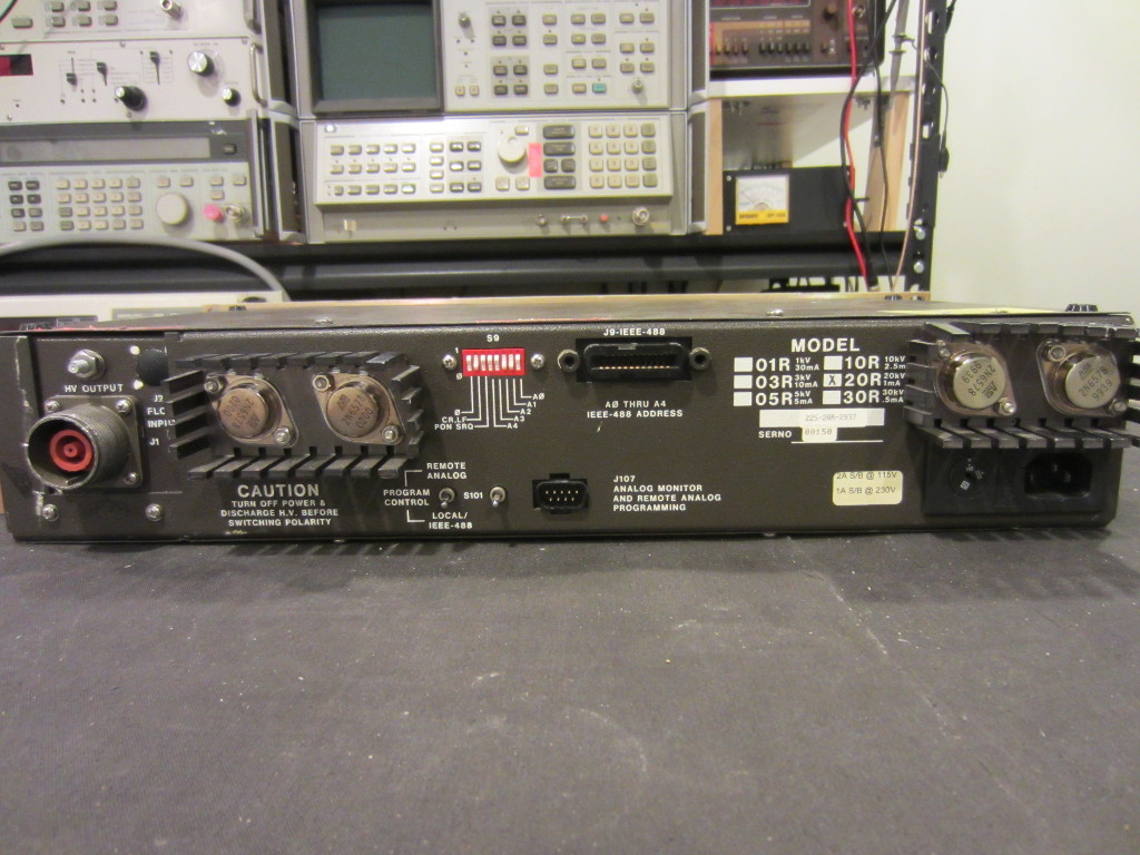
The form factor of the 225 series is identical to that of the 205A-05R. Instead of using one pair of 2N6578 for the DC-DC converter stage in 205A-05R, two pairs are used in the 225-20R. Although the maximum output power of these two units are quite similar (20kV/1mA vs 5kV/5mA).
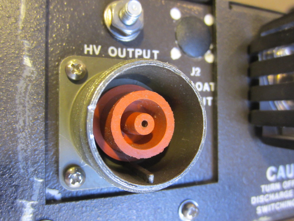
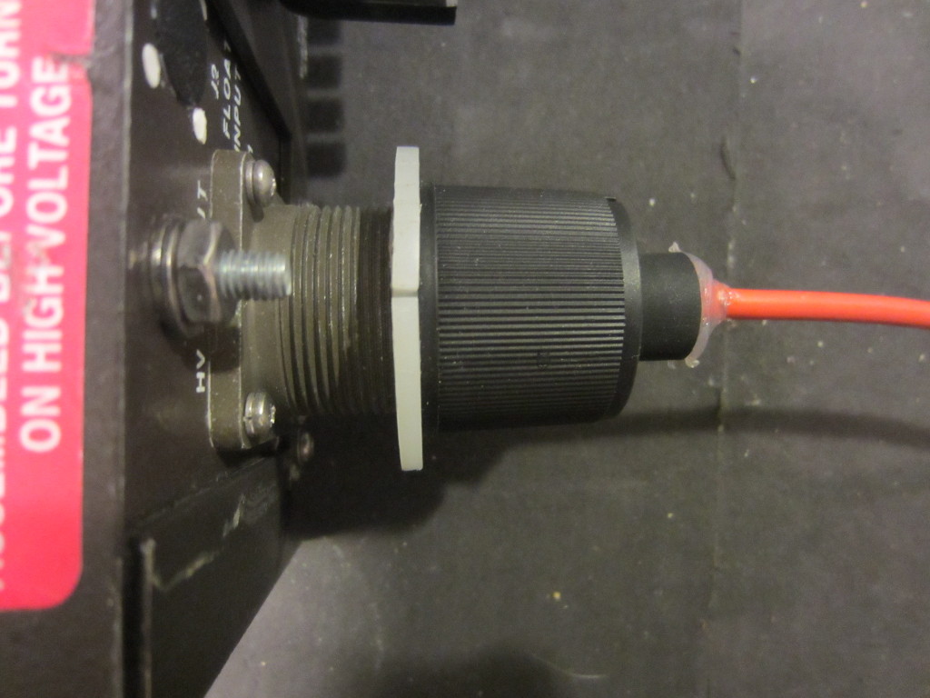
Because the maximum output voltage of the 20R model is 20kV, an MHV (high voltage BNC) connector is no long sufficient. The picture below shows the high voltage connector used in this 20kV power supply. I am not quite sure what this connector is called. It is roughly 1 inch in diameter and has two concentric rubber shrouds to prevent arcing. If you have more information on this connector type, please leave me a comment.
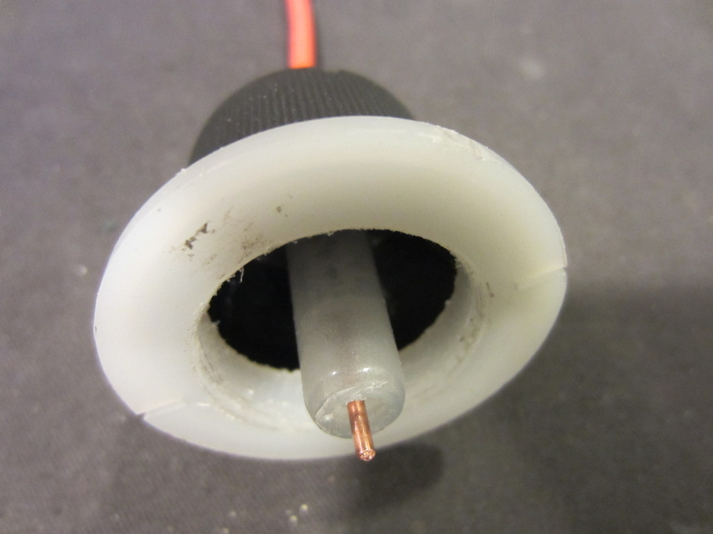
This power supply did not come with a mating connector, since I could not figure out what kind of connector it was I had to make my own. Luckily, it is not too difficult to come up with a DIY version. Here is the one I made with a plastic bottle cap, a section of a plastic tube and some high voltage wires. It serves the purpose well.
|
|
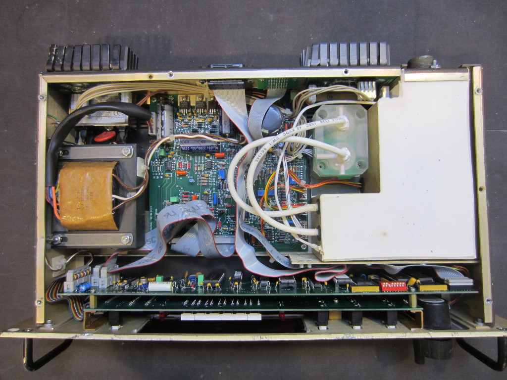
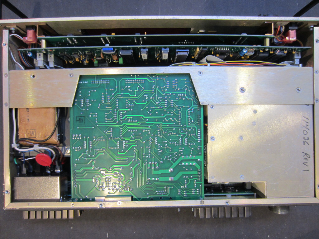
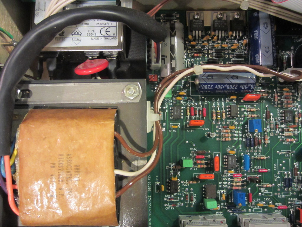
The pictures below are the top and bottom views after the panels are removed. The large potted section towards the right houses the high voltage DC/DC converter and transformer. The acrylic block in the upper center section can be manually reversed. It controls the output polarity (switch between center positive or center negative).
|
|
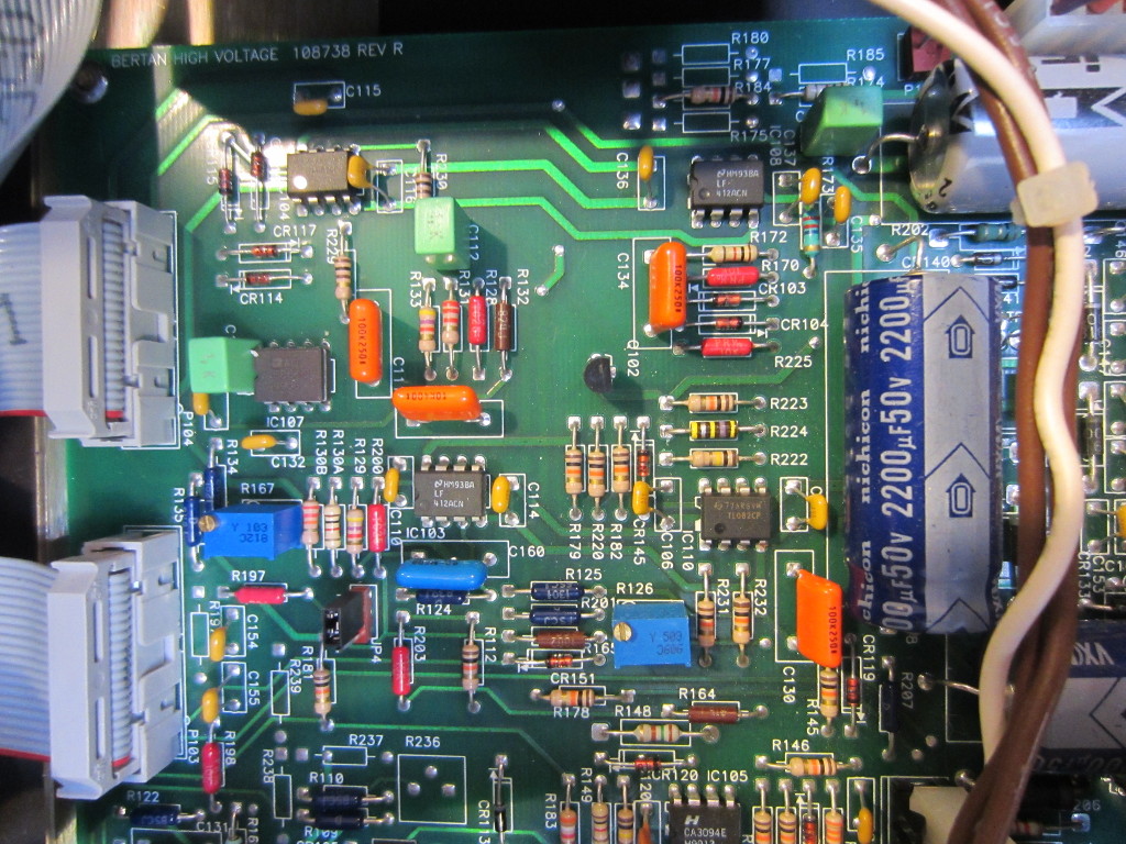
Here are a couple of pictures of the main analog board and the power supply section. Besides some OpAmps and regulators, there is not too much going on here.
|
|
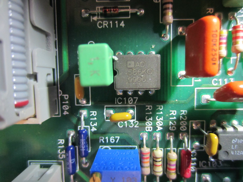
Here is a picture of the voltage reference chip located on the main board. It is a AD586K 5V precision reference, with a 15 ppm/°C temperature coefficient. Most ICs in this unit were manufactured during or before 1999, which suggest that this power supply was also made back then.
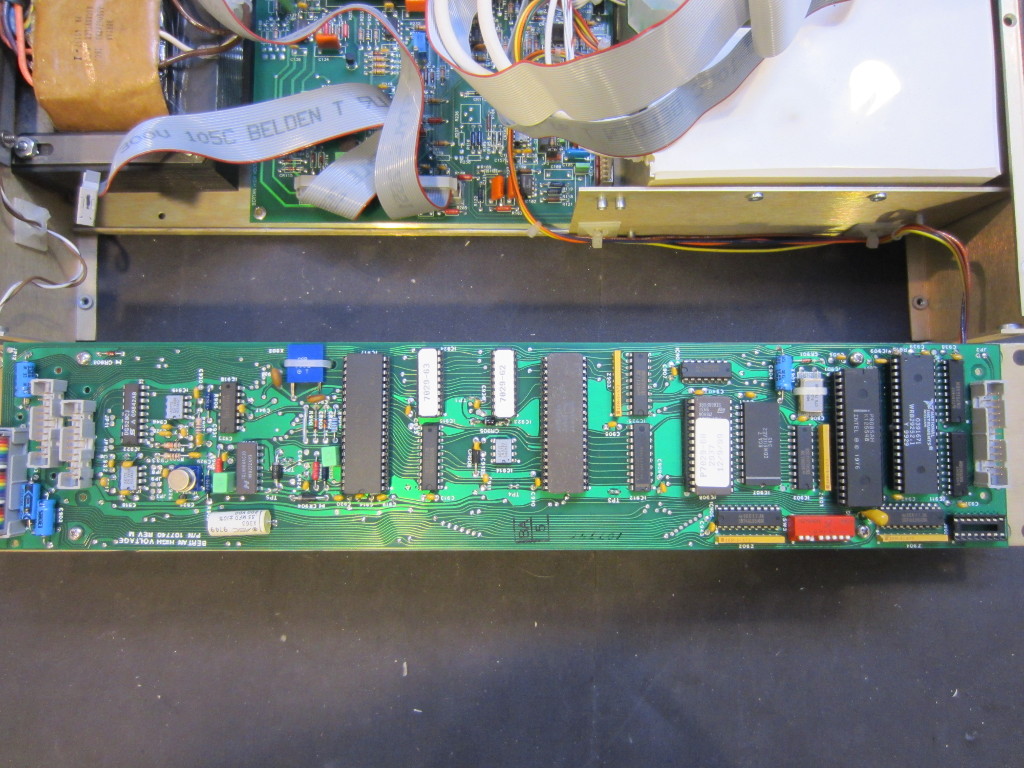
All the digital circuitry is located on the board mounted on the back of the front panel. There are actually two boards stacked together, one houses the circuitry for the display and keyboard input, the other one is the brain of the power supply which is shown here.
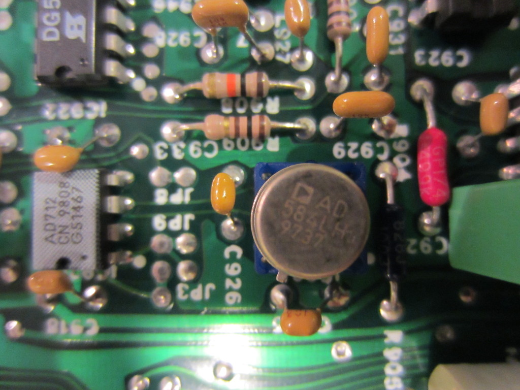
The metal can in the picture below is another precision voltage reference IC, AD584L. The “L” version has a very impressive temperature coefficient of 5ppm/°C. These precision, low tempco and low drift voltage references are essential for the stability of the HV output.
Also located on the digital board is a 14-16 bit ADC ICL8068. Given the 0.1uA current resolution and 1V voltage resolution, at least 15 bit of resolution is needed for the read back.
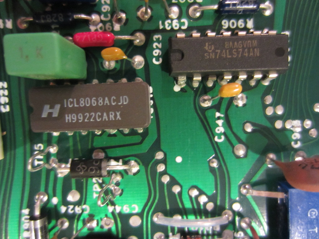
Another 14-16 bit ADC ICL7104 is also located on the digital board. Depending on the design of the power supply, one ADC could be used for current sensing and the other could be used for voltage readback.
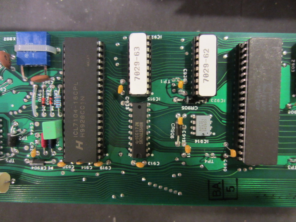
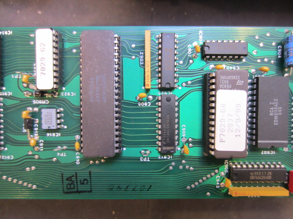
The DAC onboard is an AD7546 16 bit DAC. Again, to guarantee a 1V voltage resolution the output DAC needs to have at least 15 bit of resolution.
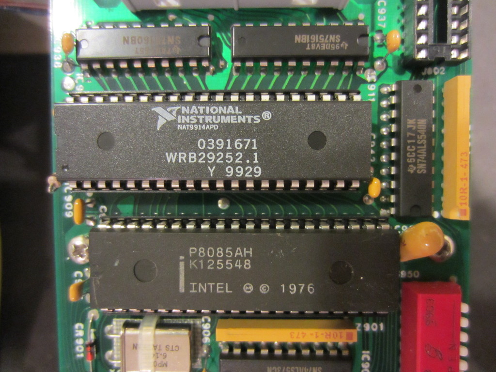
The main processor used is an Intel P8085AH microprocessor. Note the datecode on the chip, while almost all other ICs were made in 1999 but this 8085 was actually made in 1976!
In the video below, I did a walk through of the internals of this power supply and also included a few interesting experiments:

