I picked up a non-working Racal-Dana 1992 Frequency Counter on eBay a few weeks ago. The symptom is that only channel C seems to work correctly and neither channel A or channel B produces any measurements. Since the majority of circuitry is shared among all three channels, it is most likely that the fault is localized within channel A and/or channel B. In this blog post I included many teardown pictures taken during the repair and a video detailing the process is included towards the end.
Racal-Dana 1992 universal counter has three independent inputs. Channal A can measure from DC up to 160 MHz, channel B can measure from DC up to 100 MHz and Channel C has a range from 40 MHz all the way up to 1.3 GHz. Besides frequency measurements, frequency ratios between two signals can be measured via channel A and B or channel C and channel B. Phase relationships between two signals can also be obtained via the A/B channels.
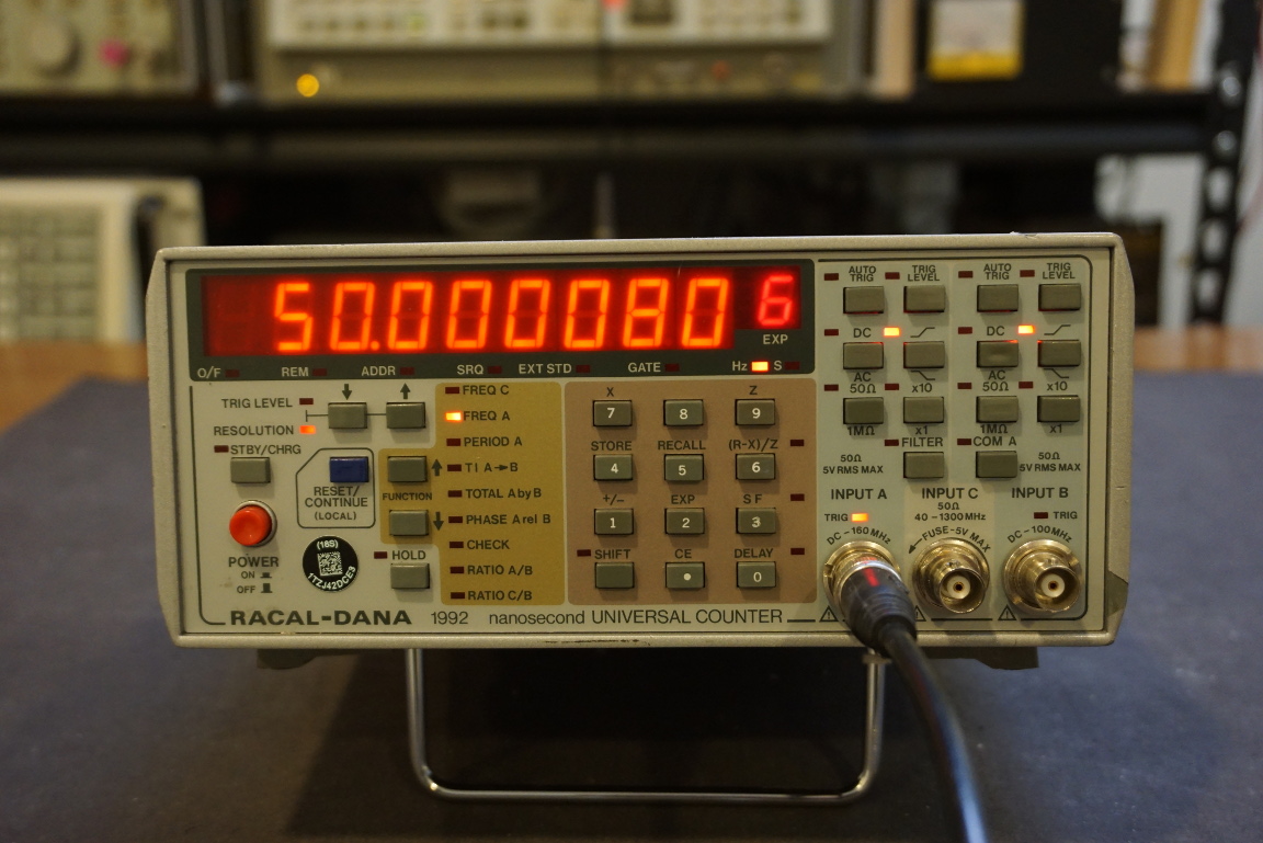
The picture below shows channel A measuring a 50 MHz square wave from my Wavetek 395 arbitrary waveform generator after it has been fixed.
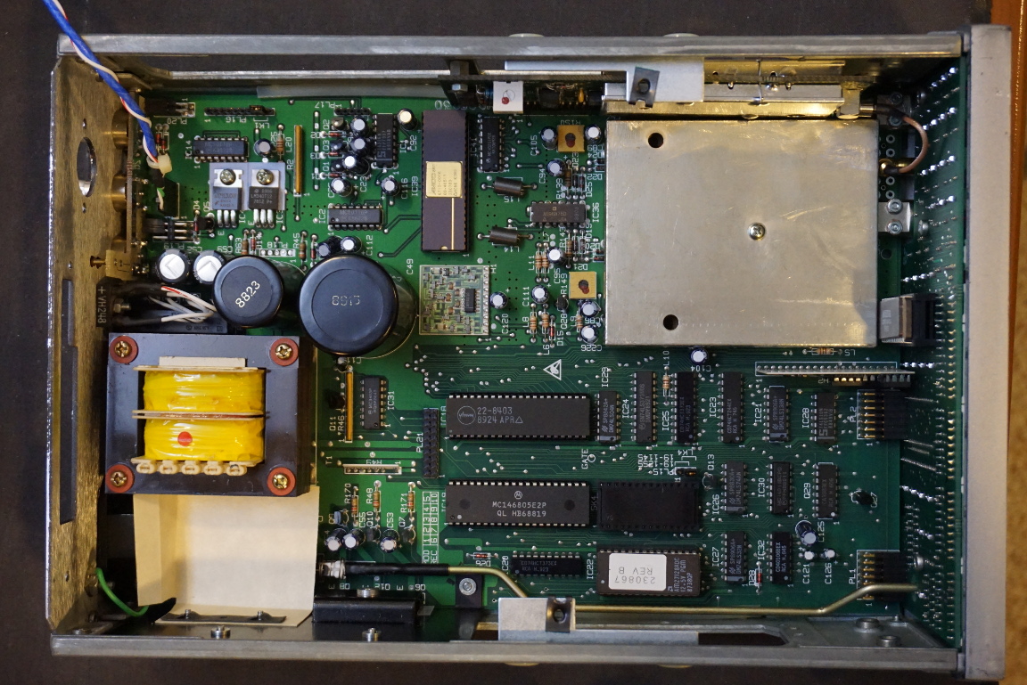
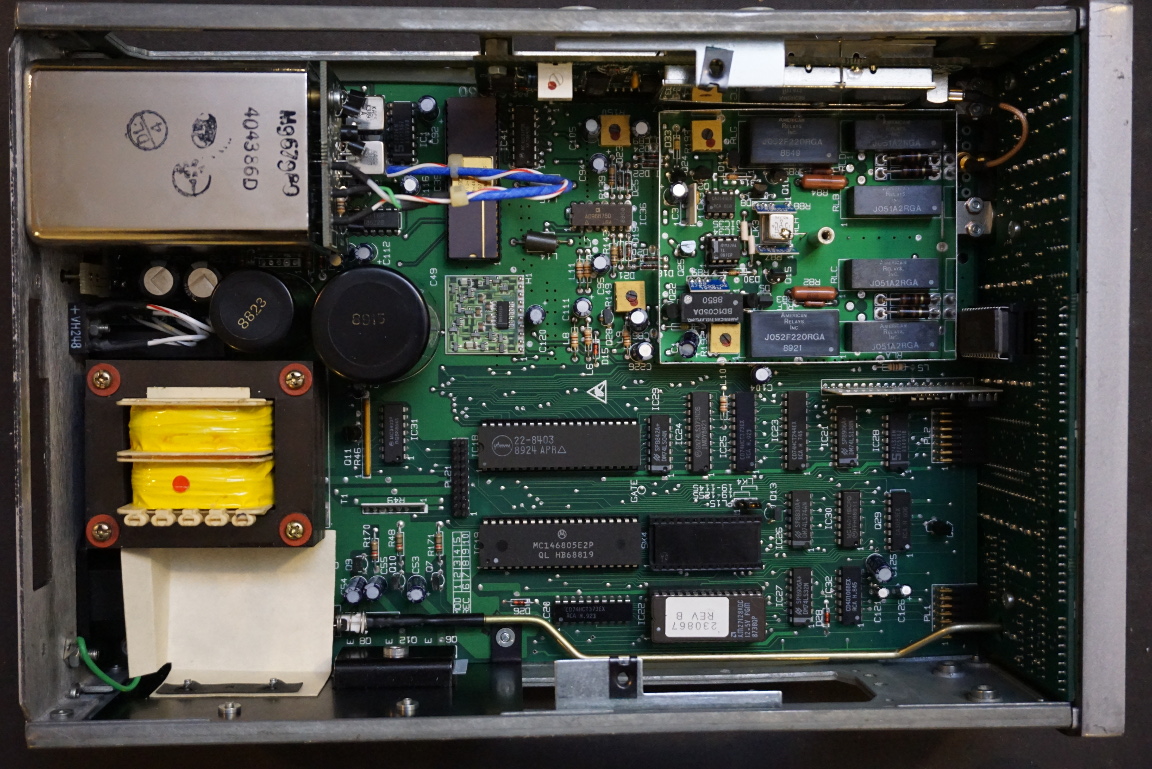
The unit I bought has both the GPIB option (option 55) and the high stability ovenized crystal oscillator (option 4E). The picture to the left below shows the internal boards layout with the top cover of the instrument removed. The picture to the right reveals the main boards with the top GPIB board and the crystal oven removed.
|
|
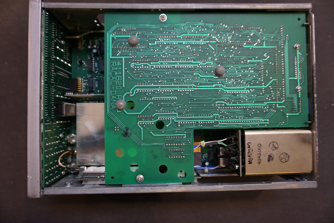
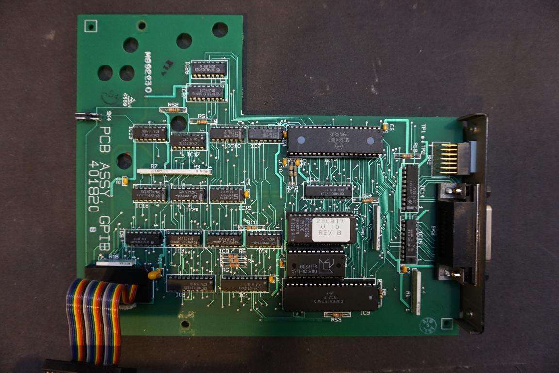
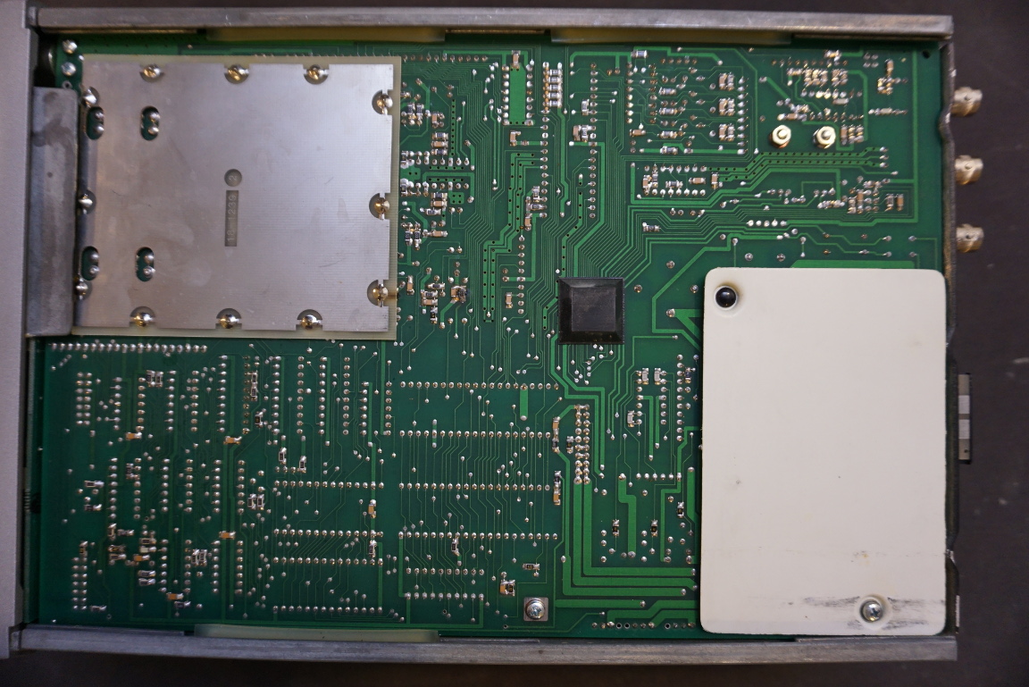
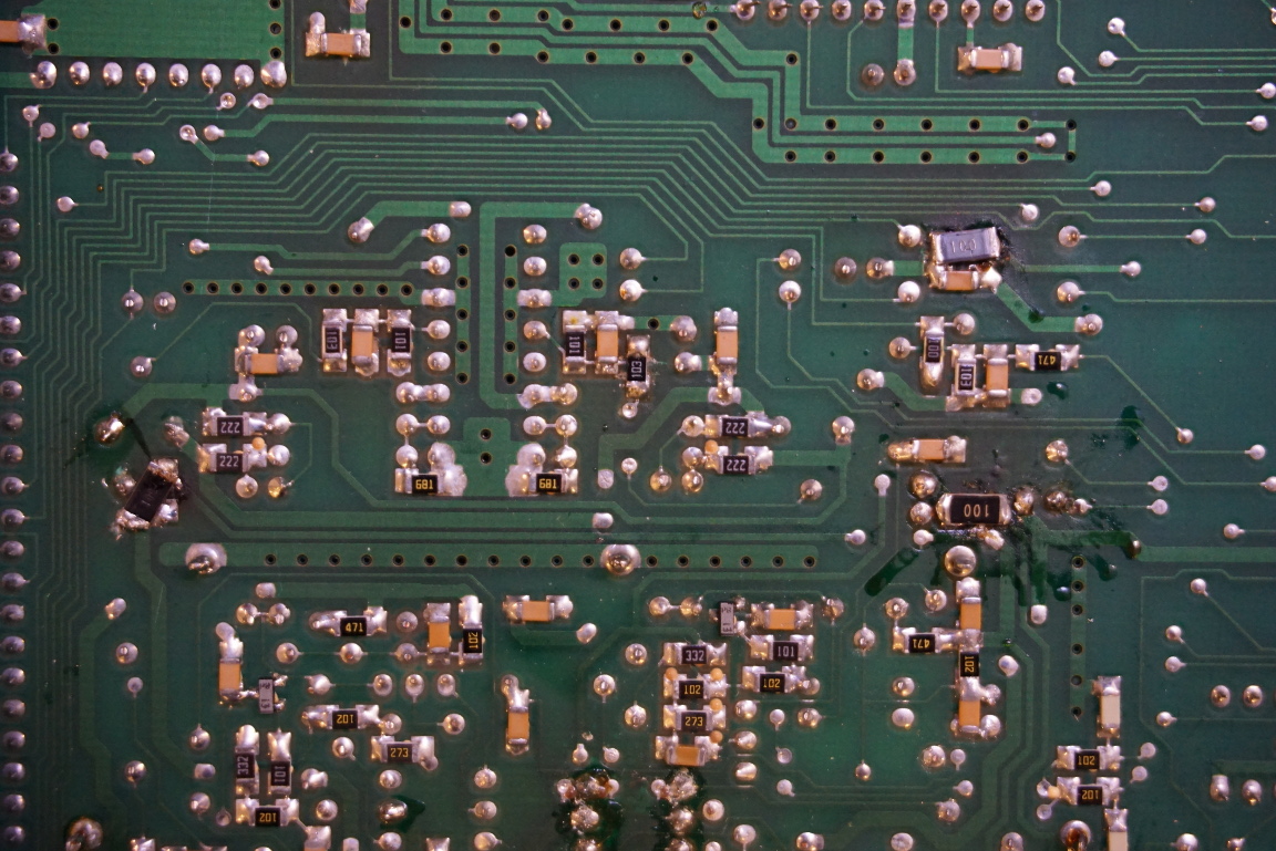
The GPIB board uses an Motorola MC68488P general purpose interface controller chip along with a CDP6805 microprocessor. The integration level of the GPIB board is quite low. The bottom side of the main PCB can be seen from the picture to the right. The input circuitry for channel A and channel B is shielded to prevent interference. The area where the mains enters the board is also covered to reduce the risk of electrical shock during servicing.
|
|
The picture to the left below shows the front panel PCB. The shielded vertical board to the left is the channel C board. The picture to the right shows a close up of the channel C board.
|
|
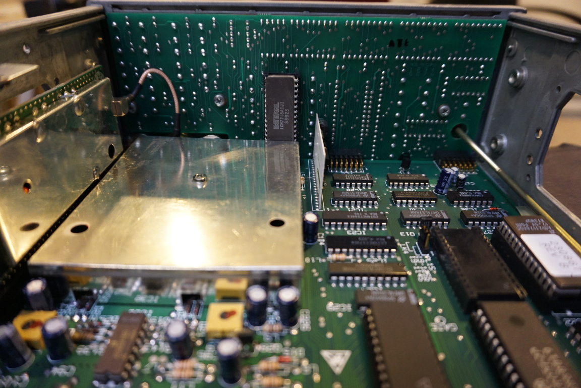
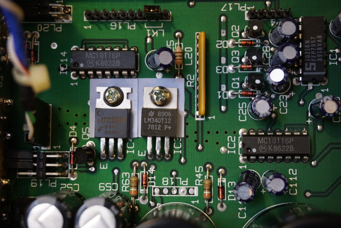
I removed the the crystal oven so I could see what was underneath it. Well, besides a couple of linear regulators there is not much else going on here. Mounted on the side panel towards the back are a couple of power transistors. Again, the mains receptacle is covered although it is just a thick piece of cardboard.
|
|
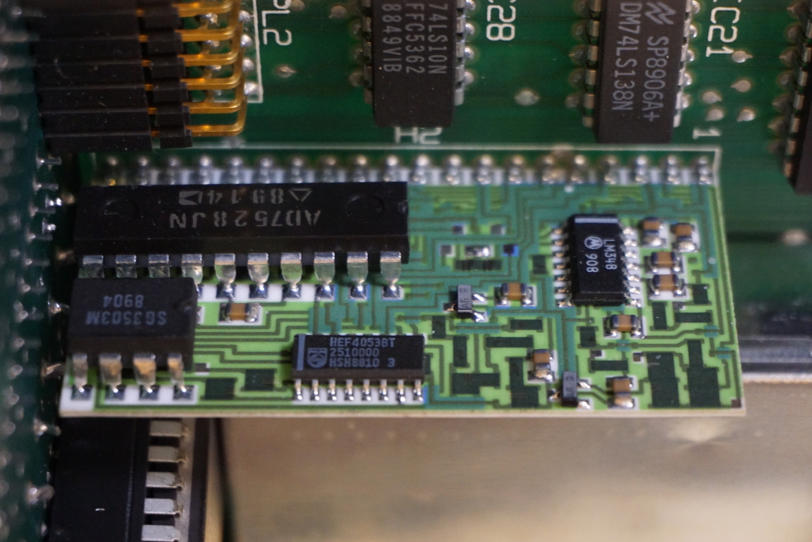
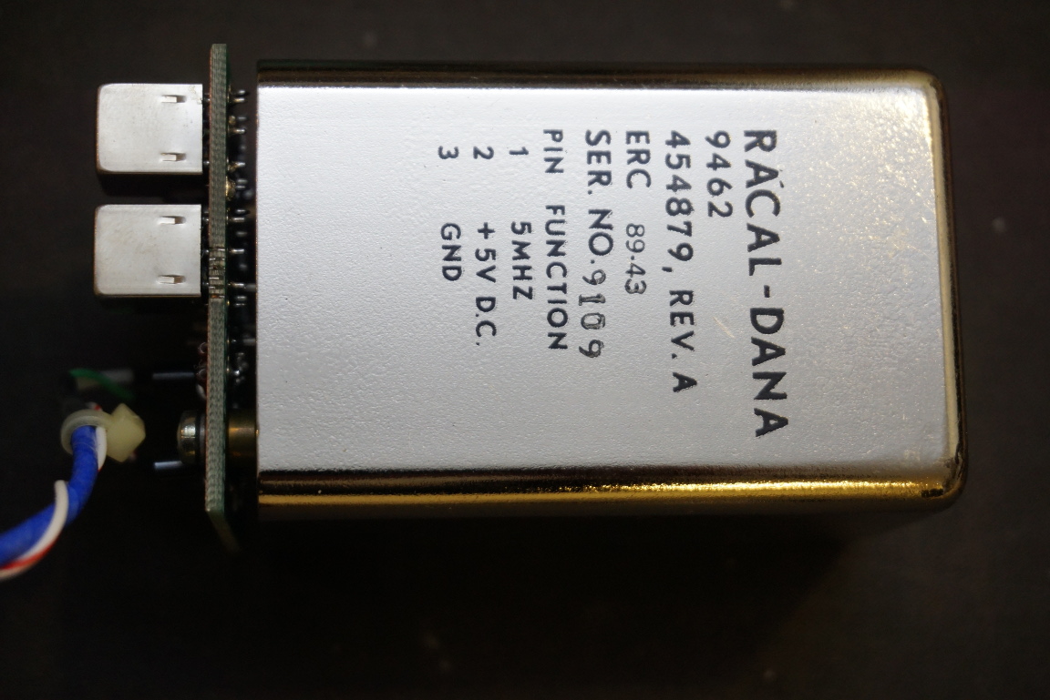
The vertical board shown below houses an AD7528 which is a dual 8-bit multiplying DAC. The voltage reference used for the DAC is a Microsemi SG3503 2.5V precision reference. Note that the carbon resistors are printed directly onto the PCB. The OCXO used here is a 5 MHz one, the frequency is doubled to produce the 10 MHz reference.
|
|
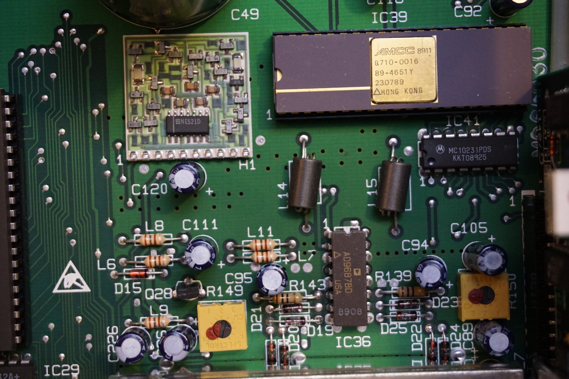
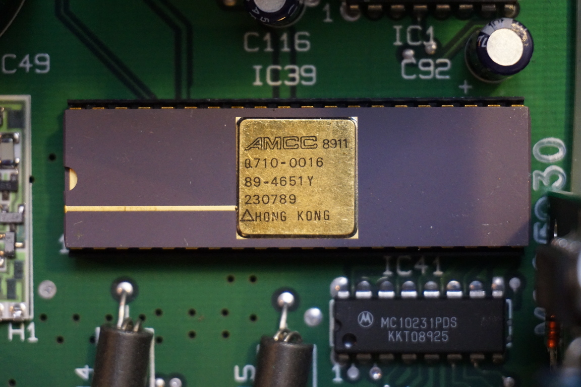
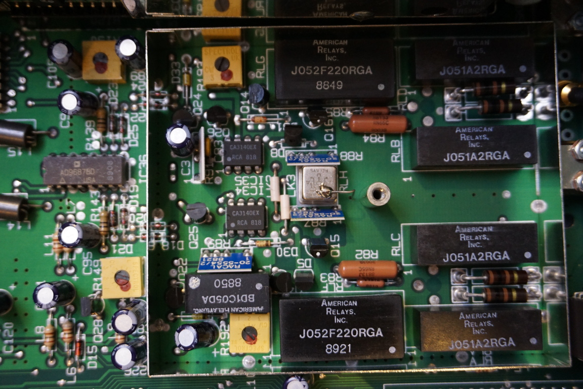
Racal Dana 1992 uses three custom chips (two for multiple counter and control and one for timing error correction) and you can see one of those below:
|
|
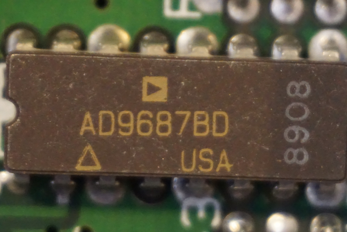
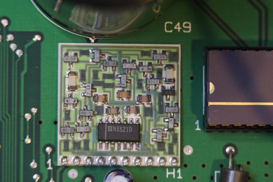
Here are a couple of closeups. The ceramic chip AD9687 is a dual ultra-fast ECL-output comparator. The image on the right is a NE521 high−speed dual−differential
comparator board. Again, all the resistors are printed onto the board.
|
|
| [adsense] |
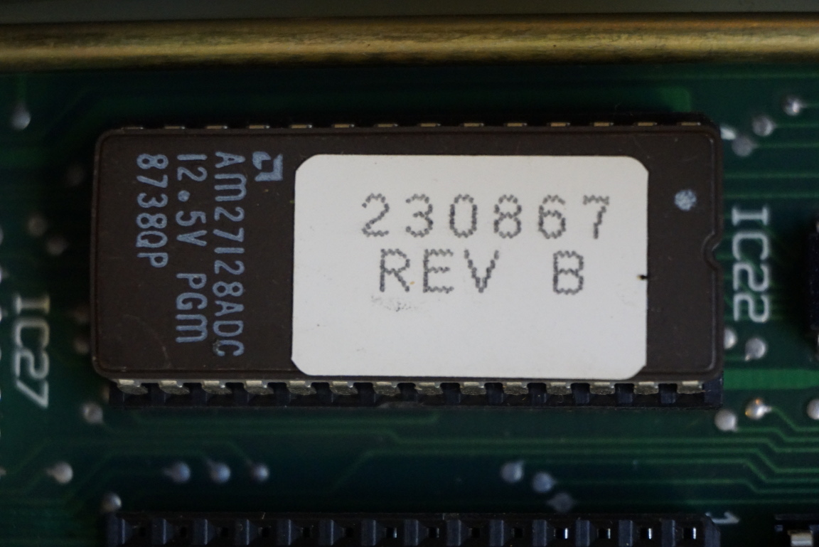
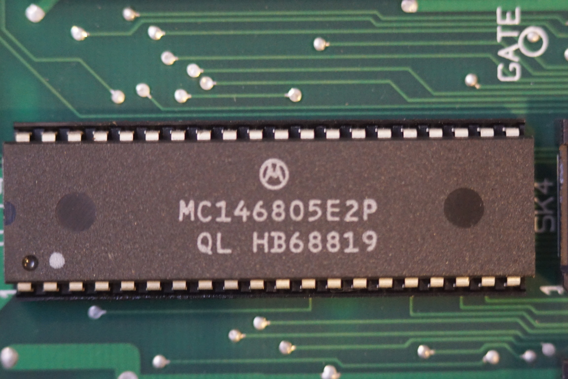
The main microprocessor on the board is another 6805 variant MC146805. Interestingly, the EPROM for the main program is only 128 kb whereas the EPROM for the GPIB controller board is 256 kb.
|
|
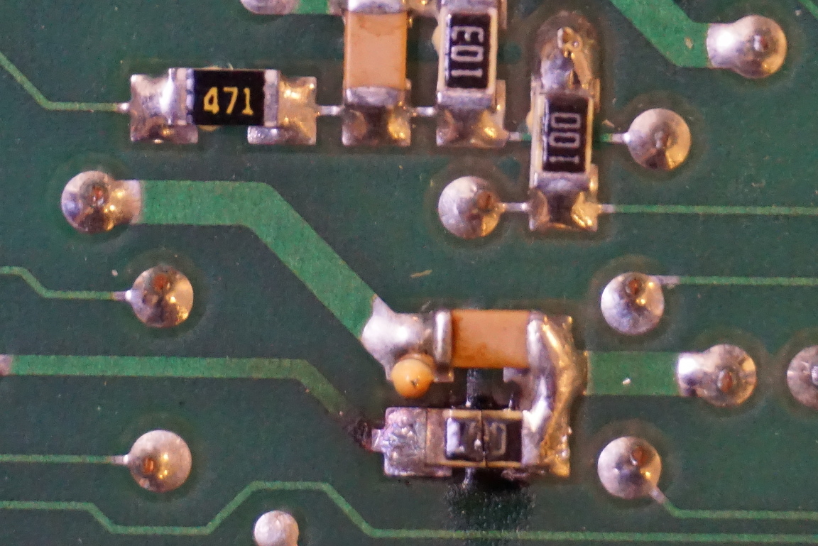
The picture below to the left gives a hint at what might have caused the failure of the channel A and channel B. One of the resistors (it’s a 10 Ohm resistor) is clearly burnt due to excessive current passing through. This resistor is between Vcc and the rest of the channel A circuitry, which suggests that something is possibly shorted within channel A. In the picture to the right, you can see that the burnt resistor had been replaced. I didn’t have any 0402’s so I used a 0603 10 Ohm resistor for the replacement. A couple of 10 Ohm resistors on channel B also looked suspicious (their measurements were a little off) so I replaced those in the process as well.
|
|
The main culprit which caused a short between Vcc and Vee in channel A is the OpAmp in the preamp stage. The resistance between pin 7 and pin 4 (Vcc and Vee) of the CA3410 measured at 34 Ohm which clearly suggests that the OpAmp had failed. Since the OpAmp’s power supply rails connect directly between the 10 Ohm resistor and the power rails, a 34 Ohm resistance means that the current draw would be close to 800mA and it’s clearly above the limit of what a 0402 resistor could handle. Since I do not have any CA3140’s lying around I replaced it with a similar OpAmp, a TL081. The main difference between these two OpAmps is that on CA3140 pin 8 is a strobe pin and can be used to strobe the output whereas on TL081 pin 8 is left unused. Since pin 8 is not used in the circuit, this replacement worked out to be just fine.
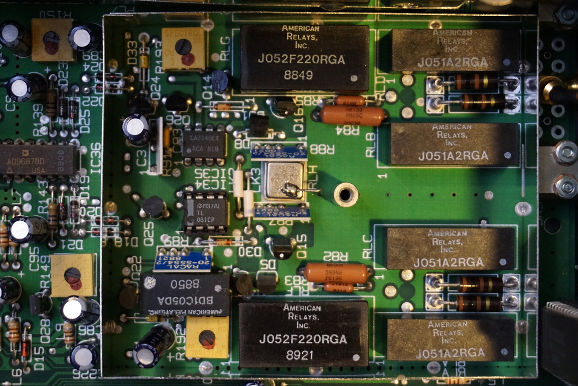
In the picture to the right below, you can see the replaced TL081 seated in an IC socket.
|
|
Here is another picture showing the inside of the Racal-Dana 1992 before I put the shielding cover back on.
Finally, if you are interested in this repair you can watch my video linked below. I also covered some fundamentals on how different types of frequency counters work.

