I finally got my hands on a Rubidium frequency standard. I have been wanting to get one of these for my lab for quite some time now but have not encountered a good one at a reasonable price. Most rubidium oscillator modules on the second hand market these days come from decommissioned equipment used in cell towers. A good used lab grade rubidium standard is even more expensive.
The unit I bought from eBay is a Datum/Symmetricom 8040 Rubidium frequency standard from the late 1990s. It is not in the greatest shape physically and was well used, but it can still achieve a frequency lock within a few minutes. So for my occasional use, it is more than adequate.
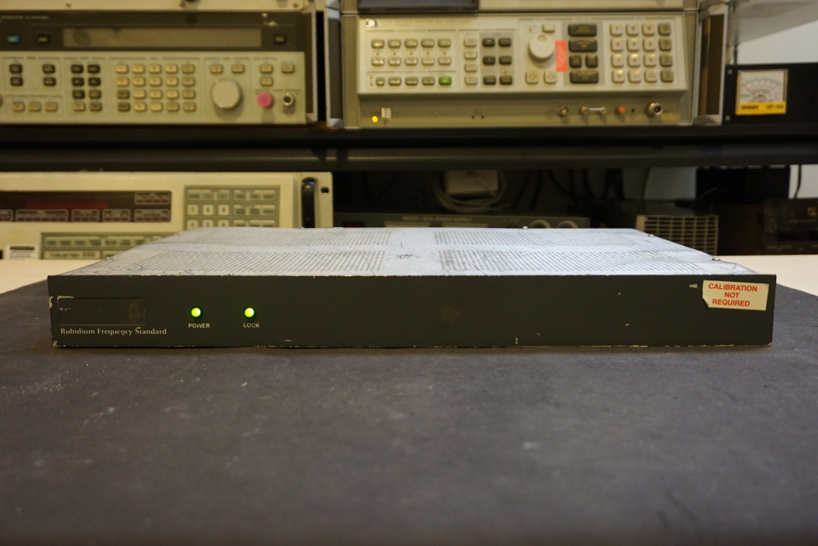
The 8040 used an LPRO 101 (low profile Rubidium oscillator) oscillator. Interestingly, there is a note written on the top of the LPRO case: “vibration test may have magnetized cover”. As you may know, Rubidium standards’s accuracy is very sensitive to external magnetic field. But it shouldn’t be an issue for me as the drift caused by magnetism is usually in the sub milli-Hertz range and even the most sensitive frequency counter in my lab won’t be able to pick up this minute drift.
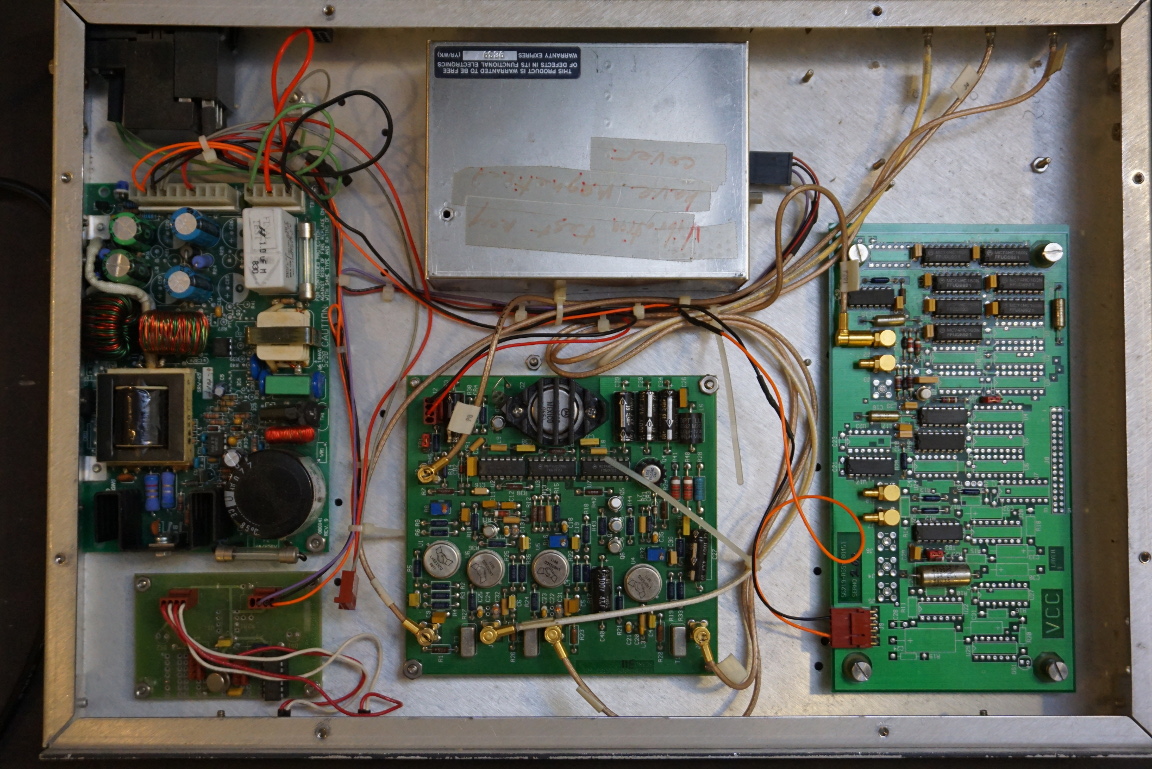
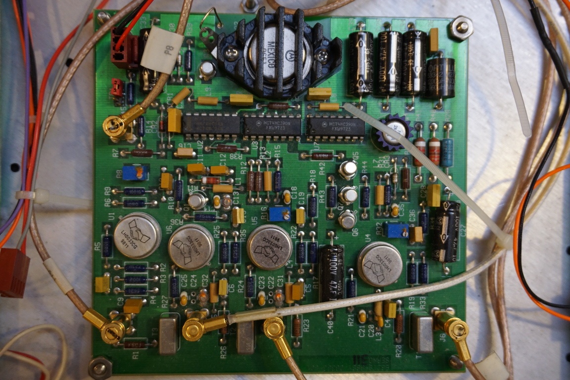
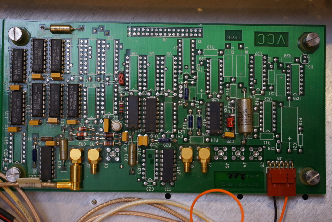
Two counter/buffer boards are used to provide reference outputs of various frequencies (10MHz, 5MHz, 1MHz and 1Hz). The sinusoidal outputs (10MHz, 5MHz and 1Mhz) are provided via the circuit board shown in the picture below. Two 74HC390 binary ripple counters are used to divide the 10MHz frequency from the LPRO 101 down to 5MHz and 1MHz. The four metal cans are fast buffers (LH0033). These buffers have a slew rate of more than 1500V/µS and can provide up to 100mA drive current, which are ideal for providing a 50 Ohm output impedance for all the clock output signals.
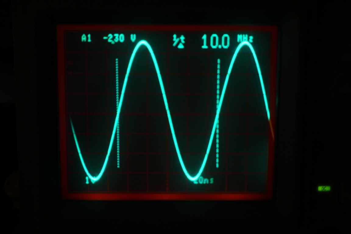
Here is the waveform of the main 10MHz reference output from the rear BNC:
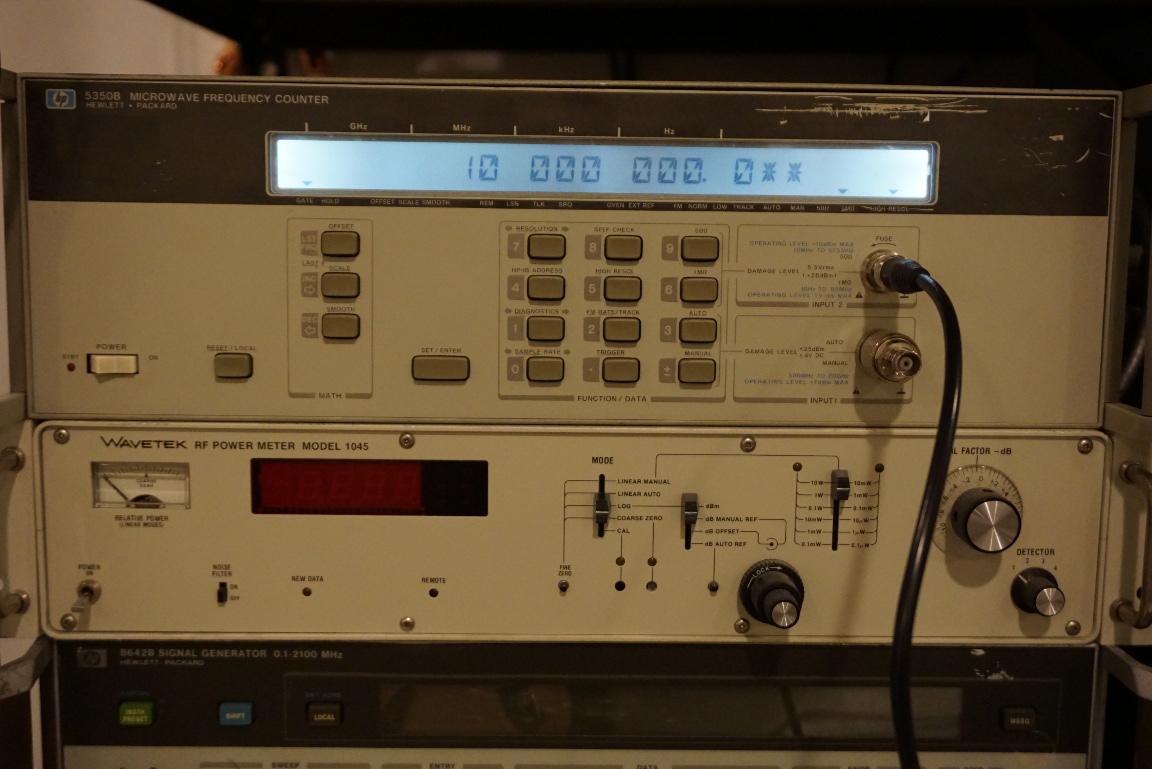
And here is the locked 10MHz frequency output from the 8040 measured against a recently calibrated HP5350B frequency counter.
A separate board provides the 1PPS output using 7 74HC160 decade counters. The output from this board is TTL only. The 8040 I got doesn’t appear to be using this board as when it first came neither the power nor the coax was connected to the board, but it appears to be working fine. The output 1PPS signal is a very short pulse with a duration of just 20µS.
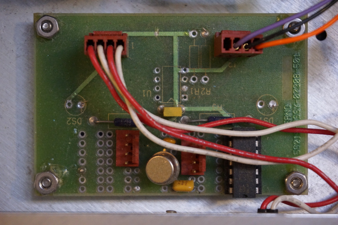
Here is a picture of the logic board that power’s the Rubidium frequency lock indicator using the lock signal from the LPRO.
And finally, here is a video detailing the teardown:

