My video on the teardown of an HP 493A traveling wave tube amplifier had generated quite a bit of interest. After I revealed that the electron gun portion of the tube was radioactive, a couple of my YouTube channel viewers had wondered if I could take the traveling wave tube further apart. So I did just that.
As mentioned in my previous post, the tube portion is surrounded by cylindrically stacked-together magnets lengthwise to help shape and focus the electron beam and I wasn’t able to disassemble much further last time because of the tight coupling between the magnet and the tube itself.
To help dissipating heat generated within the traveling wave tube during operation, a layer of thermal grease was applied between the glass tube and the magnet sleeve. And over time this layer hardens and the tube became “stuck”. After some fiddling, I eventually managed to take the tube out without damaging the tube further (I did break the cathode portion off during my initial teardown as I mentioned in my video). And here is a picture of the dissembled traveling wave tube (the model number for this tube is Watkins-Johnson WJ-3502-1).
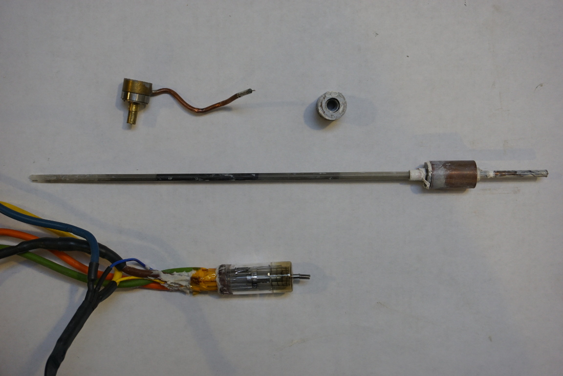
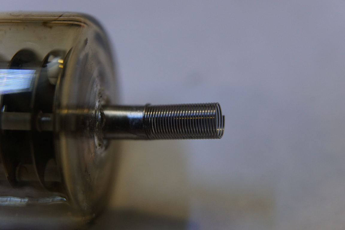
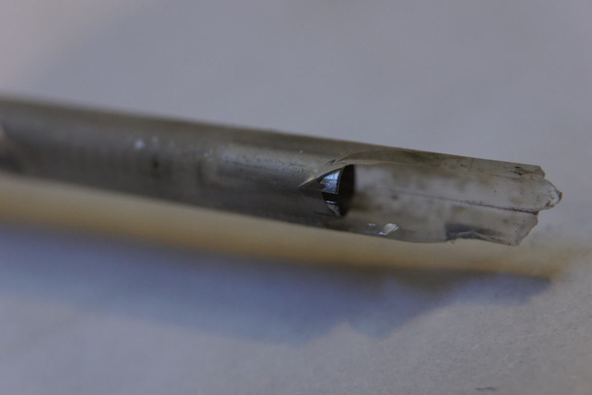
Below are a couple of closeup pictures of the electron gun portion of the tube that broke off during disassembly. Note the springy structure protruding from the electron gun. I previously had thought that this was part of the helix structure. But with the TWT disassembled, it became clear that my assumption was not entirely accurate.
|
|
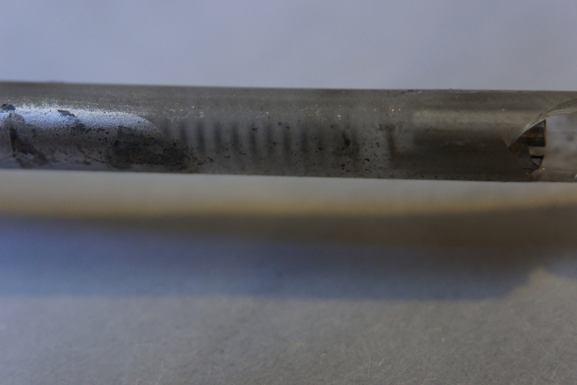
As it turned out, the springy structure was used to ensure good electrical contact with the metal sleeve inside the narrow tube as you can clearly see from the picture below. To put the dimension into perspective, the outer diameter of the tube is roughly 3 mm.
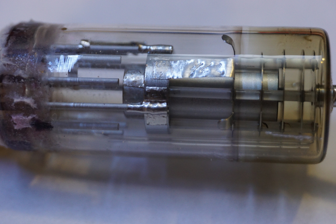
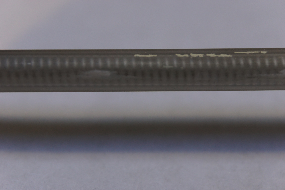
The helix structure starts after the short mating section and the pitch of the helix is considerably coarser than the springy contact. You can see the helix clearly in these two closeup pictures below. The tube itself is darkened by either some gas absorbing coating or the sputtering of cathode material over time.
|
|
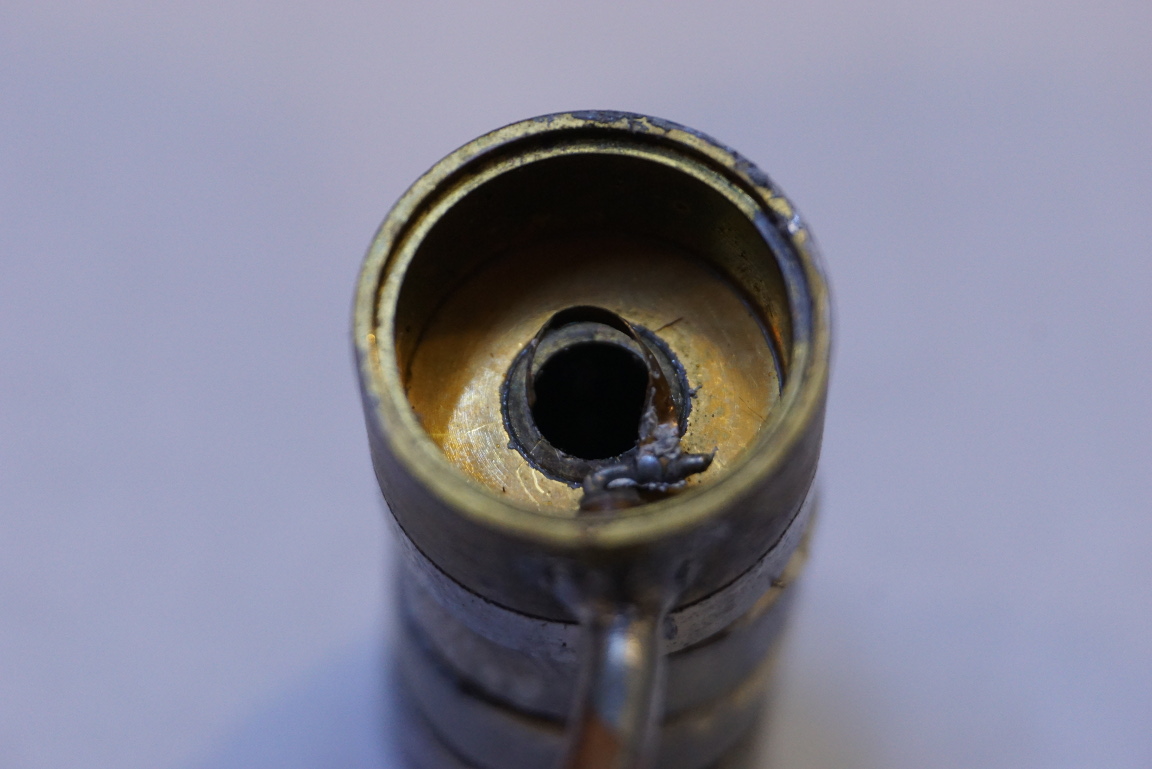
Perhaps the most intriguing part of this traveling wave tube is how the RF signal gets coupled into and out from the helix structure. As it turned out, the coupling was done outside of the tube via brass coupling rings. The picture below shows the ring for coupling the amplified RF signal out into the coax from the helix structure.
This design makes sense as both the RF input and RF output are electromagnetically coupled and therefore no physical contacts are necessary. by placing the coupling rings outside the tube it greatly simplifies the tube design and improves reliability as we no longer have to worry about sealing the electrodes.
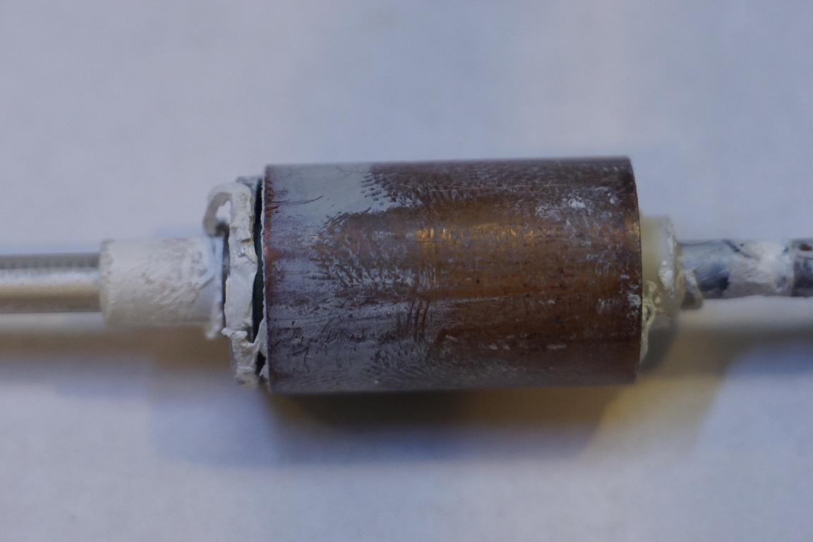
As for the anode, there is nothing exciting to see here. The collector is simply a piece of metal (copper or brass maybe?) pellet embedded towards the end of the tube. To help dissipate the heat generated when the accelerated electron beam hits the anode, the anode section is pressed against a large copper cylinder which in turn is thermally coupled to the aluminum casing.