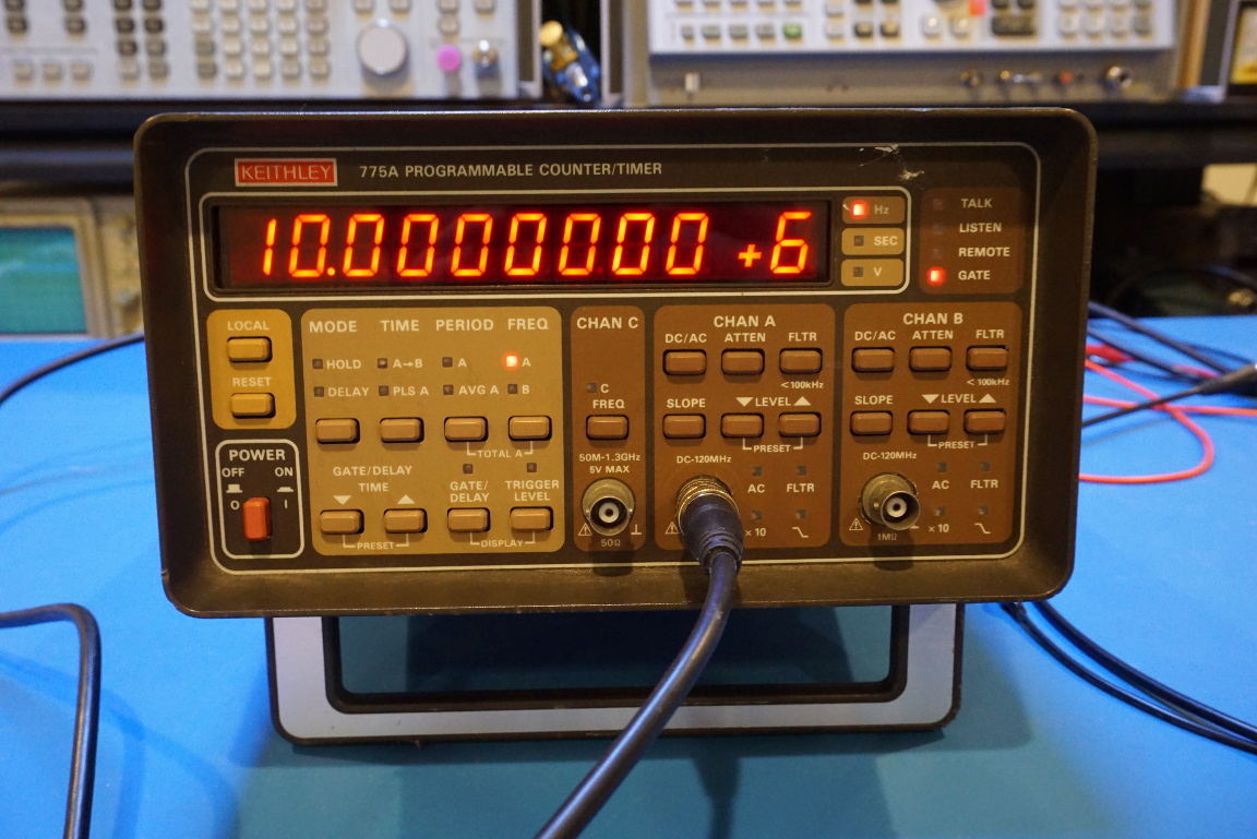
In my last post, I did a teardown of the Keithley 775A programmable counter/timer. And while feeding a 10 MHz signal from my Rubidium frequency standard, I noticed that the measured frequency was significantly lower (9.9981 MHz) than the nominal 10 MHz reading and could not be compensated by adjusting the TCXO fine adjustment screw alone. My suspicion quickly turned to the temperature controlled crystal oscillator (TCXO).
This is not the first time I had to examine a timebase. When I first got my HP 5350B microwave counter a few years ago I noticed that the oven was never up to temperature and after dissembled the OCXO I realized that the fusible resistor was blown. So that was a quick and straightforward repair, how about this time?
Crystal oscillators do drift over time and the particular TCXO used in the Keithley 775A only had an adjustable range of a few Hz and thus once the frequency drifted too far out, we can no longer calibrate it by using the on-board trimmer capacitor alone. Although mechanical shock can sometimes correct minute drift (up to 0.01 PPM according to literature), it could also result permanent damage to the crystal structure. Also, the direction of the drift via shock could not be inferred in advance. In any event, the drift of this TCXO is simply too large to be corrected by mechanical means.
|
|
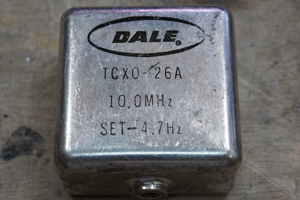
Of course, the simplest way to bring the frequency counter back in spec is to just swap out the TCXO for a a good one. But I was curious to see what’s inside this DALE TCXO-26A and see if there is anything I could do to revive it.
The TCXO could be desoldered from the daughter board without too much difficulty, but the oscillator itself was welded shut as you could see in the pictures above and the only way I managed to open it up was to use a Dremel and carefully cut along the seam around the welded edges. If I manage to fix the TCXO, it wouldn’t be too difficult to weld the case back together.
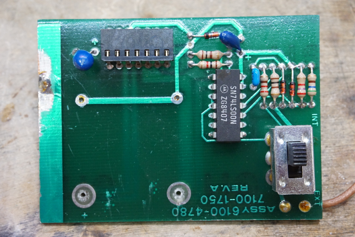
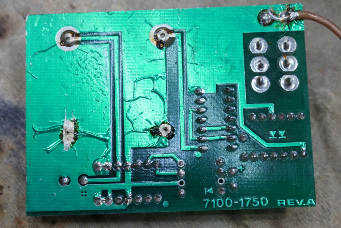
Here are a couple of pictures showing the daughter board after the TCXO had been removed. You can see that the internal and external reference selection is done via a manual DPDT switch.
|
|
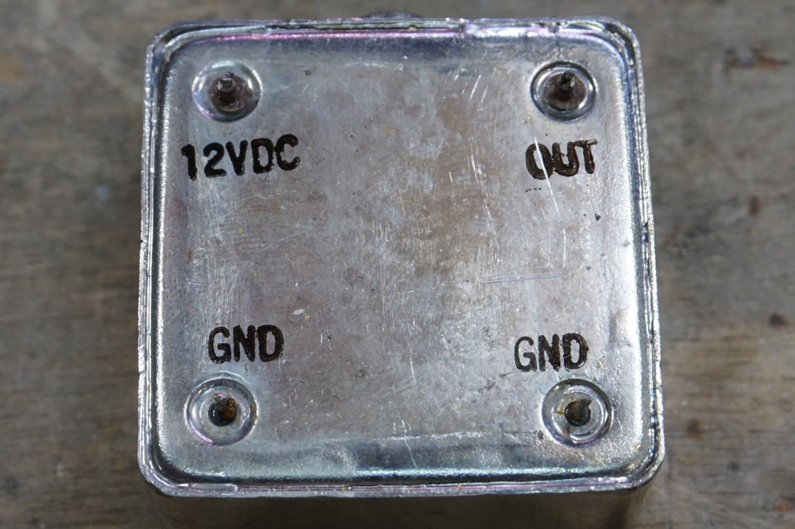
And here is a picture after the TCXO had been freed from the metal housing. The bottom metal plate is still connected via the four feed-through terminals.
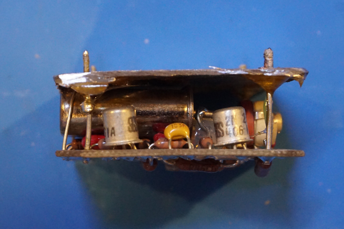
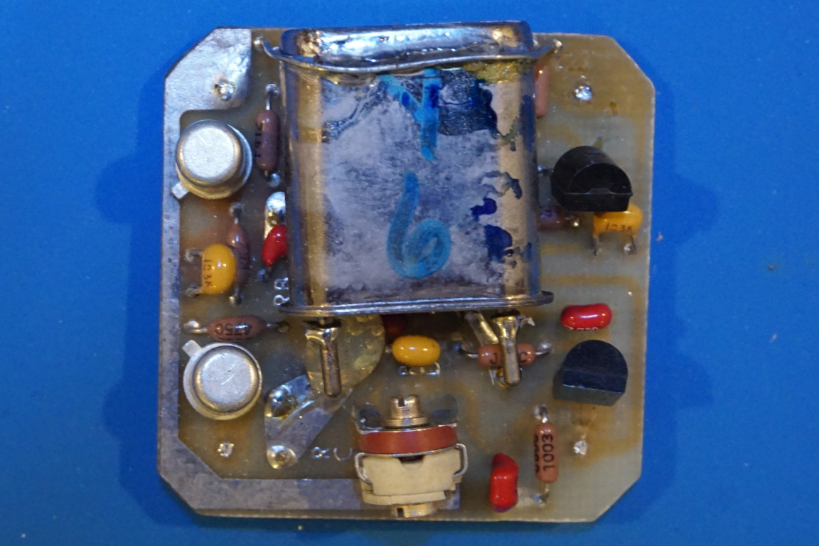
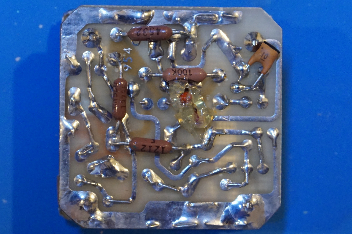
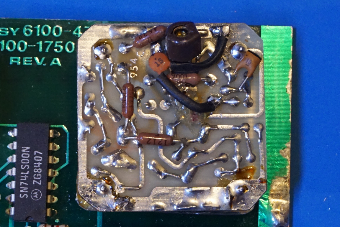
Here are a couple of pictures showing the TCXO board. The 10 MHz crystal used is rather large in size. And a quick measurement by connecting the TCXO directly to a 12V power supply confirmed that the TCXO’s output is significantly higher than the 10 MHz nominal output.
|
|
To bring the frequency back down, my simple solution was to add an additional trimmer capacitor from one lead of the crystal to the circuit ground so that I could use the load capacitance to fine tune the crystal’s resonant frequency.
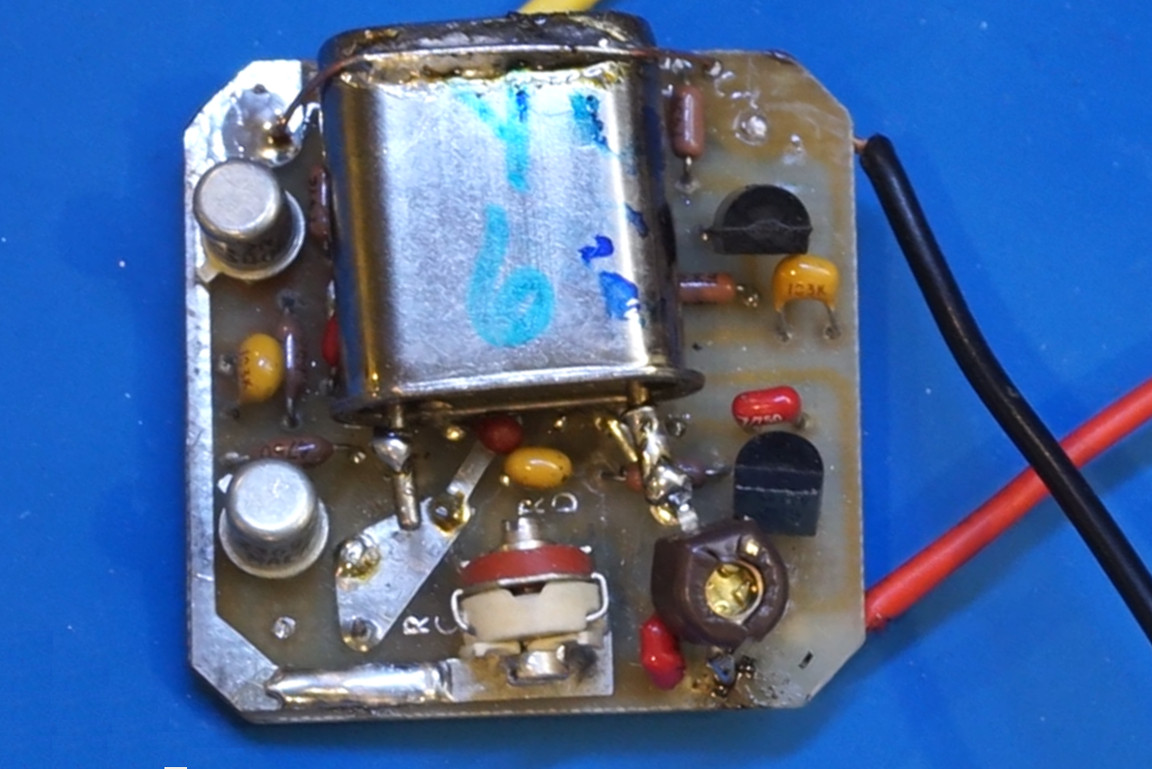
Originally I was going to use just a single trimmer capacitor, but then I realized that the stock trimmer could only adjust the frequency up to hertz and it would be very difficult to fine tune the add-on capacitance once the bottom plate is soldered back on. So in the end, I soldered on a 10 pF capacitor along with another trimmer in parallel with the original trimmer capacitor to allow wider frequency adjustment range.
And after the modification to the TCXO was done, I powered up my Keithley 775A and readjusted the TCXO using my Rubidium frequency standard and I was able to calibrate the TCXO (see picture below).
Of course, the long term stability of this modification is yet to be seen. I will probably eventually replace it with a new TCXO, but for the time being the frequency counter is in spec again. Here is a short video showing the repair process.

