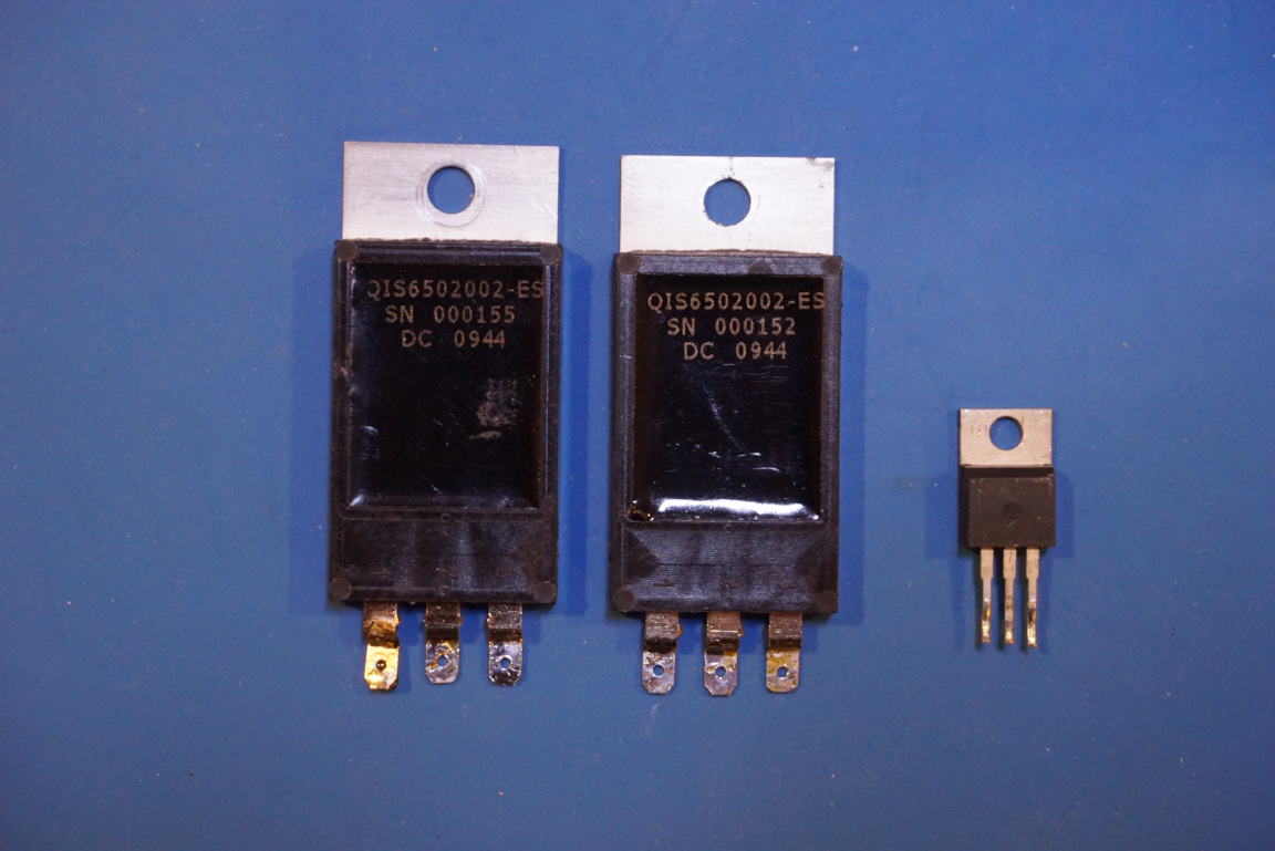
I was doing some experiments which involves switching high voltages (>3 kV) under high current (>30 Amps) load. Although solid state devices such as SCRs (Silicon Controlled Rectifier, or Thyristor) or IGBTs are the ideal candidates for this kind of operations, the prices for these devices are through the roof (1, 2) when the breakdown voltage exceeds the 3kV threshold. I did have a couple of QIS6502002 6500V 25A IGBTs I bought on eBay many years ago but as it turned out they were quite fragile, a few minor overloads during my experiments was enough to destroy them unfortunately.
So I turned my eyes to Thyratrons. These are a type of vacuum tubes (to be precise, gas-filled tubes) from the early 1900’s and have been largely replaced by its semiconductor counter part (SCR) nowadays, except for applications where extreme high voltage/high current are needed such as in pulsed radars.
Luckily, many of the medium powered thyratrons can be found on eBay at a fraction of their original cost. And as any vacuum tubes, they are quite forgiving. They can withstand quite a bit of abuse without being destroyed.
The one I picked up is a TGI1-50/5 hydrogen thyratron. As the name suggests, it uses ionized hydrogen gas as the switching medium. Hydrogen thyratron typically utilizes titanium hydride in it’s reservoir and the hydrogen gas is released when the reservoir is heated and recombined into titanium hydride when the temperature cools down. Like many other hydrogen thyratrons, the TGI1-50/5 has a separate heater for the hydrogen reservoir.
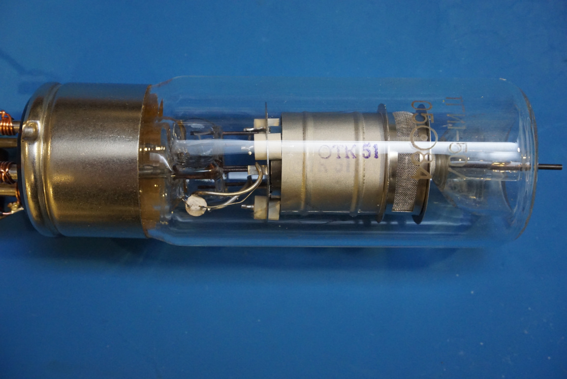
The heater element for the hydrogen generator and the cathode filament can be powered independently for fine controlling the hydrogen gas pressure during operation. Some literature suggests that the the triggering sensitivity can be precisely controlled by fine tuning the gas generator voltage. From my limited testing, as far as the TGI1-50/5 tube is concerned, the hydrogen generator voltage can be set to be the same as the filament voltage (6.3V) and the tube can be triggered reliably via a 300V pulse applied to the grid.
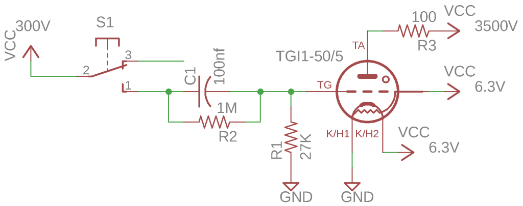
The schematics above shows my test circuit. A 100 Ω power resistor is connected to the anode to limit the maximum current to be within the specified maximum (50A). The triggering pulse is formed via C1 and R1 with a time constant of roughly 3 ms. The actual values of the RC components is not very critical in this experiment setup as the pulses are triggered manually via a momentary switch. But to achieve the fastest pulse rate, the triggering pulse width should be as short as possible (4-12 µs according to the datasheet). The datasheet does mention the minimum pulse amplitude should be no less than 150V. Again, the actual triggering voltage does not seem to matter much as long as it is above the minimum specified value.
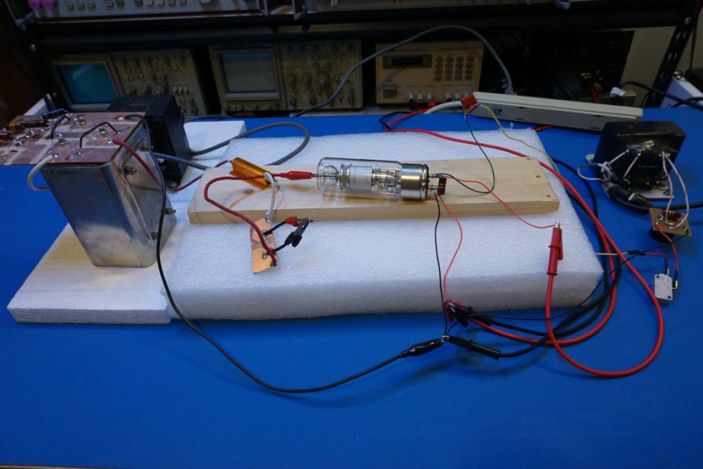
I did not have a proper socket for the thyratron so loose wires were used to wrap around each individual pins. The picture below shows the setup of the experiment. The ~3500V for the anode is doubled from a 1700V tube supply I had using a bridge doubler.
Some thyratrons require the grid to be negatively biased, but for the TGI1-50/5, a zero bias worked just fine which greatly simplified the overall circuit.
Here is a video showing the experiment setup and the firing of the hydrogen thyratron.

