I did a teardown of a BK Precision 4011 5MHz function generator a few weeks ago. Like most of basic function generators in old days, BK 4011 does not offer frequency sweep as an option. What it does include is a VCG (Voltage controlled Generator) input, which essentially is just a VCO and it can be used in conjunction with an external sweep generator to generate frequency sweeps.
In this post I will show you a simple sweep generator I built. It can be used to generate both the sweep waveform and synchronization signal needed for any function generator that has a VCG/VCO input. The sweep frequency can be adjusted from under a Hertz to several kHz. The sweep waveform can be switched between linear and logrithm modes and can be easily extended to accommodate other arbitrary waveforms.
The following schematic shows how this sweep generator was implemented. For clarity, I omitted the power supply portion of the circuit on purpose.
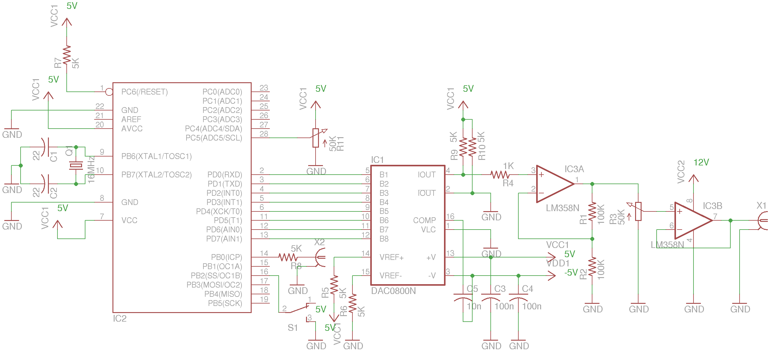
At the core of this sweep generator lies an 8-bit parallel-input DAC DAC0800. This digital to analog converter is driven by an MCU (Atmega328P) which generates the sweep waveform. The reason that I used a parallel DAC in this situation is for its speed. While DAC0800 is a rather old chip, it can operate at a relatively fast speed which makes it suitable for waveform generation use. It is also very inexpensive and easy to use. Modern DACs using serial protocols (e.g. SPI/I2C) on the other hand, can cost significantly more for the same operation speed.
One draw back of using DAC0800 is that it requires dual supply rails for operation. While there are ways (TI AN-1525) to use DAC0800 with a single supply, they add quite a bit of complexity to the circuit design. So to keep everything simple, I followed the dual supply route. To provide the negative voltage required by DAC0800 I used Maxim’s MAX889 inverting charge pump.
Because BK 4011’s VCG input range is 0-10V, the output from DAC0800 is amplified by a x2 non-inverting Op-Amp. And the output from the x2 amplifier is then attenuated by a potentiometer to obtain the full VCG voltage range. Finally, the attenuated sweep waveform is buffered through another Op-Amp. The dual Op-Amp chip used here is LM358, since it is not a rail-to-rail Op-Amp, the actual adjustable output voltage range is slightly less and will not reach 0V. For this simple sweep generator, this limitation shouldn’t matter much.
The full code listing is shown below. The code was compiled using Arduino 1.0.1, but it should be compatible with pretty much all Arduino IDE versions. The TimerOne library can be downloaded from here.
#include <TimerOne.h>
#include <EEPROM.h>

const int sweepModePin = 10;
const int syncPulsePin = 8;
const int freqValPin = 5; //analog pin 5
const int LINEAR_SWEEP = LOW;
const int LOG_SWEEP = HIGH;

int sweepMode = LINEAR_SWEEP;
int freqVal, freqValOld;
int sweepInterval = 1;

void setup() {
    pinMode(syncPulsePin, OUTPUT);
    digitalWrite(syncPulsePin, LOW);
    pinMode(sweepModePin, INPUT);
    digitalWrite(sweepModePin,HIGH);

    freqVal = analogRead(freqValPin);
    freqValOld = freqVal;
    sweepInterval = 1 + freqVal;

    Timer1.initialize(sweepInterval);
    Timer1.attachInterrupt(timer1Callback);
    delay(500);

    DDRD = 0xff; //set pin 0 through 7 as output
}

byte b = 255;
void loop() {
    sweepMode = digitalRead(sweepModePin);
    freqVal = analogRead(freqValPin);

    if (abs(freqVal - freqValOld) > 5) {
        freqValOld = freqVal;
        sweepInterval = 1 + freqVal;
        Timer1.initialize(sweepInterval);
    }
}

void timer1Callback() {
    if (sweepMode == LOG_SWEEP) {
        PORTD= EEPROM.read(b);
        b++;
        if (b==255) {
            b=0;

            //generate a synchronization signal
            PORTB |= 1;
            delayMicroseconds(10);
            PORTB &= 0xFE;
        }
    } else if (sweepMode == LINEAR_SWEEP) {
        b--;

        PORTD=255-b;
        if (b==0) {
            b=255;

            //generate a synchronization signal
            PORTB |= 1;
            delayMicroseconds(10);
            PORTB &= 0xFE;
        }
    }
}
Note that PORTD (digital pin 0 through digital pin 7) is used to drive the 8 bit DAC data line. This is the fastest way to manipulate the DAC as the bits in the same port can be altered in a single operation. Since Pin 0 and Pin 1 are for serial communications in Arduino, this means that you will not be able to use any serial port functions (you can still use the serial port to upload the program though). If you have to use serial port for debugging purposes, you could use pins from different ports to drive the DAC. Just remember that operations will be a little bit slower.
The synchronization pulse is generated at the beginning of each sweep via pin 14 (Arduino digital pin 8) for a duration of 10 micro-seconds. The actual sweep signal is generated via Timer 1 interrupt service routine timer1Callback(). During each interrupt, the current DAC output value is updated.
For linear sweep, the counter variable b is simply modified by one during each interrupt. A single sweep cycle consists of 256 interrupts because we are using an 8-bit DAC. The actual sweep frequency is determined by the interrupt interval, which is set via the initialize() function of Timer1. One draw back of this method though is that the sweep frequency can not be adjusted contiguously.
For log sweep, a normalized logarithm table (when the index changes from 0 to 255 the function value changes from 0 to 255 accordingly) is pre-calculated and stored in the EEPROM of ATmega328P. The counter variable b is then used as an index into the value table to retrieve the corresponding function value. Since ATmega328P has 1024 bytes of EEPROM, up to 4 sets of different sweep waveforms can be pre-programmed.
The sweep frequency adjustment is achieved via the potentiometer on analog pin 5 (chip pin 28). When a change in measured voltage value is detected, the sweep interval is changed accordingly in the main loop. In order to avoid measured voltage value variation due to noise, the threshold of the voltage change is set to 5.
The sweep speed is limited by the timer interval and number of points used to generate the waveform. For linear sweeps or waveforms that require lower resolution, higher sweep speed can be achieved by reducing the number of sample points (e.g. from 256 points to 64 points).
The following two oscilloscope captures show the linear and log sweep generator output along with the synchronization pulse respectively:
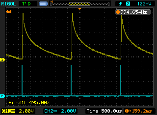 |
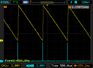 |
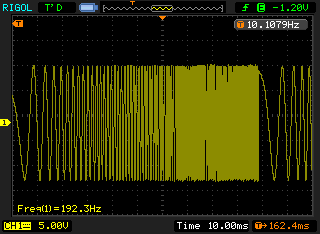
And here is a capture showing the function generator output controlled by the sweep signal input. The synchronization pulse is connected to the external trigger input of the oscilloscope for synchronization.
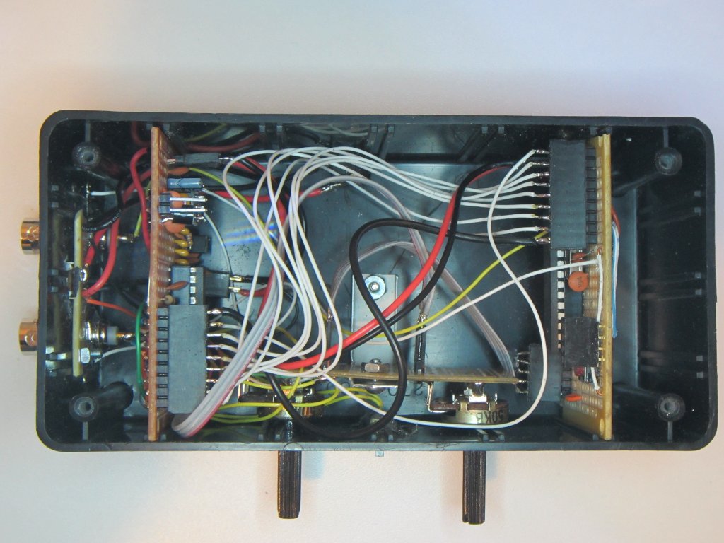
Here is a picture of everything put together inside a project box. I used two perf-boards for the circuit. The board on the left has the ADC and charge pump circuit and the one on the right has the microcontroller. The wiring is a bit messy but for the relatively low frequency the circuit is working under, this is not a big issue.