In my previous post, I did a review of the 6000 counts ennoLogic eM860T true RMS multimeter. This meter is based on a signal chip design using the versatile DTM0660L DMM chip. Besides the ennoLogic eM860T, several other multimeters such as UNI-T 139C, Velleman DV4100, Tekpower TP40 etc. are also based on the same chip.
One key feature of this chip is that most of the configurable parameters as well as the calibration data are all stored in an external EEPROM. This means that we could potentially change certain settings and enable certain settings (e.g. enabling UART communication, backlight duration, auto power off duration, etc.) by just changing values in the configuration EEPROM without having to do any hardware modifications. We will take a look at how to make these configuration changes in this post.
Since sigrok (a cross-platform signal analysis software suite) already added support for the DTM0660 chip, we can use the sigrok-cli command line utility to talk to the meter via UART/RS232 once we have the functionality enabled .
As I mentioned in my previous post, the PCB of the eM860T already had REL/PC Link printed on its silk screen, but this feature was not enabled for the meter as long press on REL button does nothing. According to the datasheet for DTM0660 (if you follow the link on sigrok’s supported devices page, you can find the datasheet hosted on a Chinese document share website, unfortunately is not in a very user friendly format), UART functionality is supported via external EEPROM configuration as well as some other functionalities.
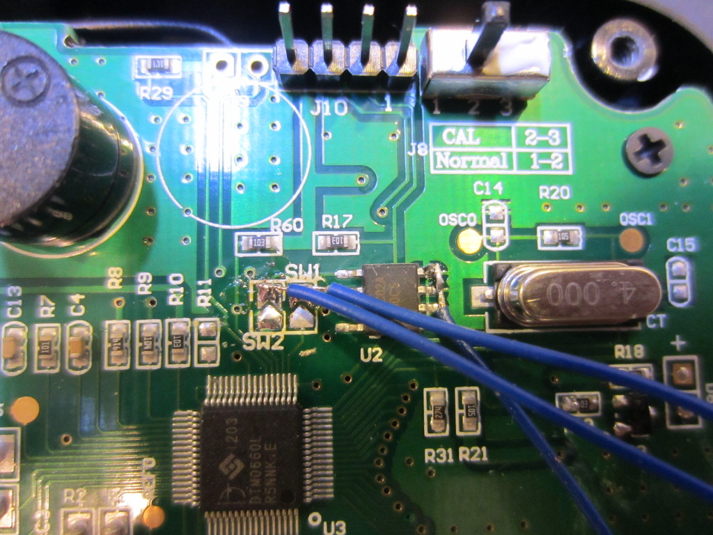
The EEPROM used in eM860T is an 24C02A. It uses I2C protocol for programming. eM860T has the I2C header populated on the PCB already, but I didn’t realize that at first. As you can see in the picture below I soldered three wires directly onto the board when I was playing around with the 24C02A. The WP pin of the on-board 24C02A has a pull-up resistor connected to VCC (e.g. the chip is in write protected mode). In order to write data to it, WP pin needed to be pulled low (in the picture you can see a wire soldered from pin 7 to ground).
Since the calibration data is also stored on the same EEPROM chip, it is highly recommended that you back up the content before making any changes. Also at least in this meter there are two solder bridges that you can remove (see SW1 and SW2 below). These bridges connect the I2C bus of the 24C02A and that of the DTM0660L together. While you don’t have to remove these solder bridges when reading from or writing to the EEPROM since these chips have different I2C addresses, it is highly recommended that you do as in the rare event if a wrong command with a wrong I2C address is issued you could inadvertently alter the content in DTM0660L (I am not sure whether this chip has any on-chip EEPROM or not, but it is always good to be safe than sorry) and brick the device.
So I went ahead and dumped the content of the 2kb in the 24C02A with the help of an Arduino (the actual code I used is included here).
#include <Wire.h>
const int I2C_ADDR = 0x50;

void setup() {
  Serial.begin(9600);
  Wire.begin();

  dumpEEPROM();
  //writeByte(I2C_ADDR, 0xFA, (byte) 0xCE); //enable RS232
  //writeByte(I2C_ADDR, 0xFC, (byte) 0x1E); //Backlight time 30s
}

void loop() {}

void dumpEEPROM()
{
  for (int i = 0; i < 256; i++) {
    byte b = readByte(I2C_ADDR, i);
    Serial.print(b, HEX); Serial.print(" ");
    if ((i + 1) % 16 == 0) Serial.println();
  }
  Serial.println();
}

void writeByte(int i2cAddr, unsigned int addr, byte data) {
  Wire.beginTransmission(i2cAddr);
  Wire.write(addr);
  Wire.write(data);
  Wire.endTransmission();
}

byte readByte(int i2cAddr, unsigned int addr) {
  byte data = 0x00;
  Wire.beginTransmission(i2cAddr);
  Wire.write(addr);
  Wire.endTransmission();
  Wire.requestFrom(i2cAddr, 1);
  while (!Wire.available()) ;

  data = Wire.read();
  return data;
}
And here is the content of the 24C02A in its entirety:
    0  1  2  3  4  5  6  7  8  9  A  B  C  D  E  F
00 FF FF FF FF FF FF FF FF FF 52 00 36 01 EC D7 03
10 10 17 38 18 44 02 6E 6E 64 64 3C 3C 0A FF 40 FF
20 46 98 E8 80 00 03 C2 01 00 80 52 80 07 80 96 B5
30 4E 02 09 2D 02 09 80 FC 0A 9B 1B 0A 8D 02 0A 00
40 00 01 00 01 00 07 98 00 64 00 64 00 64 00 00 00
50 00 80 00 80 00 80 00 80 00 80 00 80 00 80 00 80
60 E9 7F 3E 80 01 00 AA 2A 00 00 00 00 00 00 00 00
70 38 81 00 80 DA 81 E0 7C B3 01 00 00 00 00 00 00
80 00 00 00 00 00 00 13 12 10 03 0E 09 01 0C 04 07
90 00 00 00 00 00 00 15 00 11 00 0F 0A 02 0D 1E 0B
A0 00 00 00 00 00 00 00 00 00 00 00 00 00 00 00 00
B0 00 00 00 00 00 00 00 00 00 00 00 00 00 00 00 00
C0 0D 00 02 10 0D 00 03 20 20 00 03 20 20 00 03 10
D0 41 00 03 08 41 00 03 05 41 00 03 05 0D 00 02 20
E0 00 80 00 80 00 80 00 80 00 80 00 80 F8 7F 06 80
F0 00 80 FF FF FF FF FF FF 5A CB CC 0F 0F 82 00 00
Specifically, I was interested in the following three bytes (marked in red in the EEPROM dump above). According to the datasheet, here is what the values in these three locations mean:
FA: bit 1 controls whether RS232/UART can be enabled by pressing REL.
    0: function unavailable
    1: long press on REL key enables RS232/UART

FB: time before auto power-off (1~255 minutes, auto power-off is disabled if set to 0).
FC: backlight on duration (1~255 seconds, if set to 0 it's controlled by the backlight button only)
From the EEPROM dump we can see that the current settings on my meter are as below:
FA: CC (1100 1100) RS232/UART disabled
FB: 0F (0000 1111) 15 minutes
FC: 0F (0000 1111) 15 seconds
[adsense]
To enable entering RS232 mode with a long press on the REL button, the byte in FA needs to be changed to CE (1100 1110). And to extend the on time for the backlight or to increase the auto power off duration of the meter I can change the bytes in FB or FC. I wanted to set the backlight auto off time to 30 seconds so I set the content in address FC to 1E. The default 15 minutes auto power-off is fine for me so I left it alone. But for some people a longer on idle time might be more preferable and in that case the desired value in minutes for the time before automatic power down can be written to address FB.
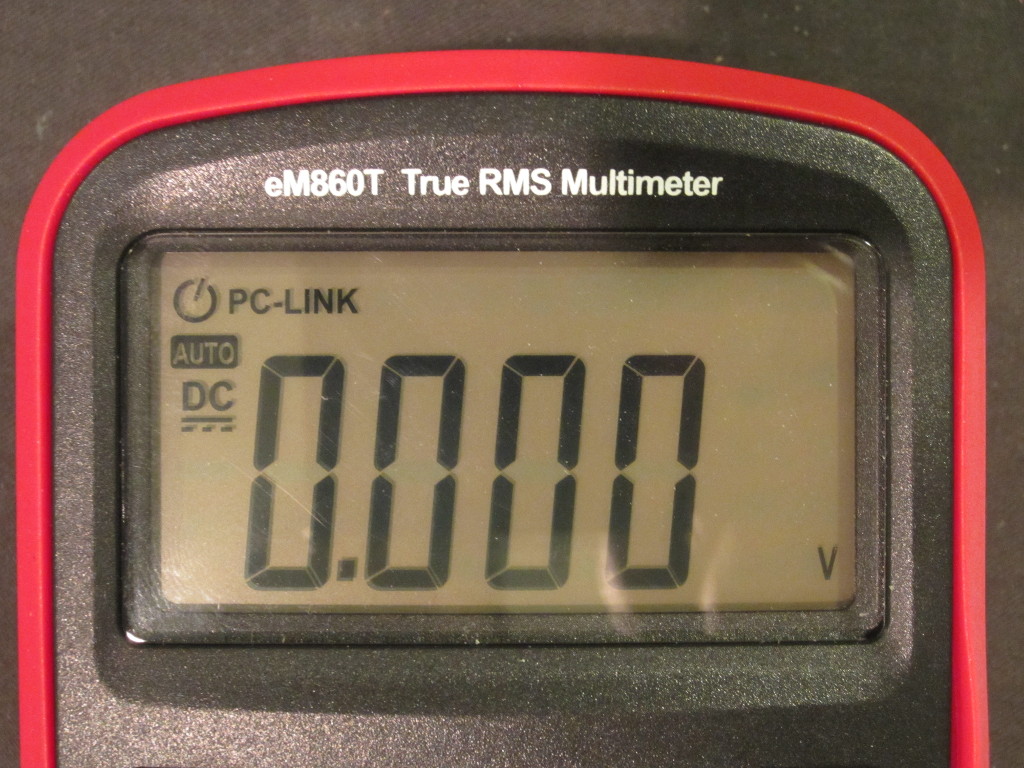
Once the UART functionality is enabled, a long press on REL will turn on the PC-link indicator on the LCD as shown here:
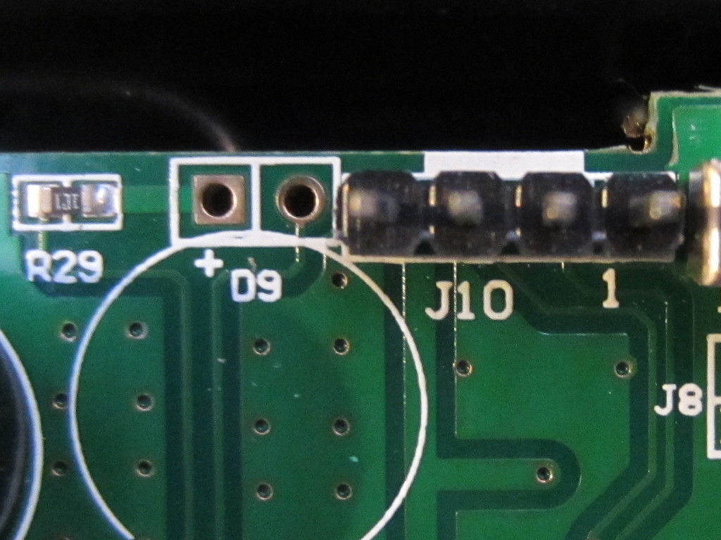
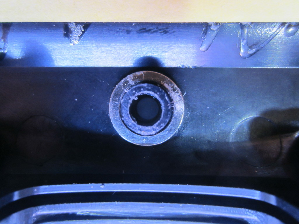
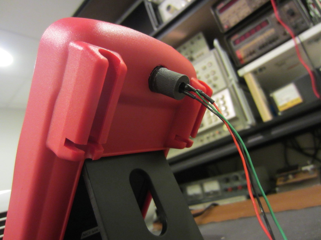
Next, I wired an IR diode onto the D9 footprint. Conveniently, the PCB already has the pads designation for the diode and it even has the current limiting resistor soldered in place. The IR diode can be mounted through the small hole on the back cover. Since the receiving IR diode will be placed directly against the transmitting diode, range and interference are not of any concerns. Thus I could get away with just a simple IR diode instead of an IR module that modulate the RS232 signal onto a higher carrier frequency.
|
|
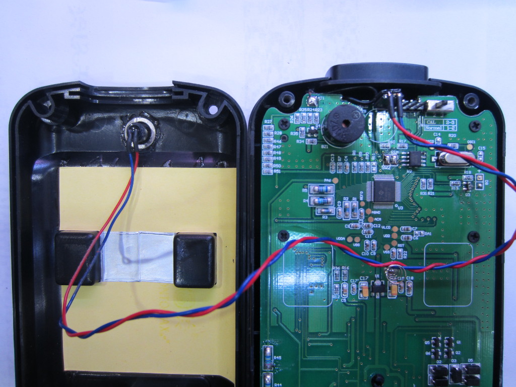
To make life a bit easier when mating an external IR receiver for data logging, I glued a ring magnet around the IR transmitter inside the case. I also had an identical piece of magnet glued on the receiver sensor side so the they can be connected magnetically.
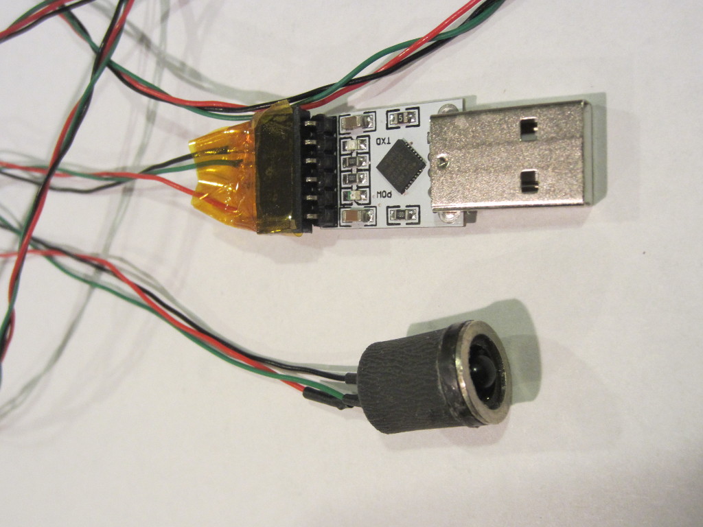
In the picture below, you can see the receiver I made. I used a section of rubber standoff for housing the IR diode and the resistor. This isolated datalink works quite well and can be connected/disconnected easily. While you could just connect the UART-to-USB adapter directly to the serial output of the meter directly, it is highly recommended that you use proper opto-isolation as otherwise you could damage the DUT, the meter and even the connected computer if the measurement is not done correctly.
|
|
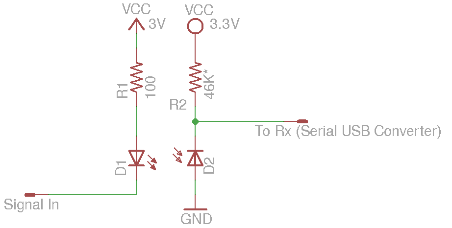
The receiver side is just an IR photodiode and a resistor since there is no demodulation involved and the transmission range is negligible. The value of the resistor is chosen such that the output voltage swings close to either supply rail. Cable length is not critical since the data rate is very low, at only 2400 bps. The transmitter and receiver circuits are included below for reference. Note that the IR emitting diode is connected between the driving signal and the positive rail, so in idle mode the IR is off. Because of this, the IR photo diode needs to be ground referenced so that the RX signal going into the UART/USB module remains high when idle.
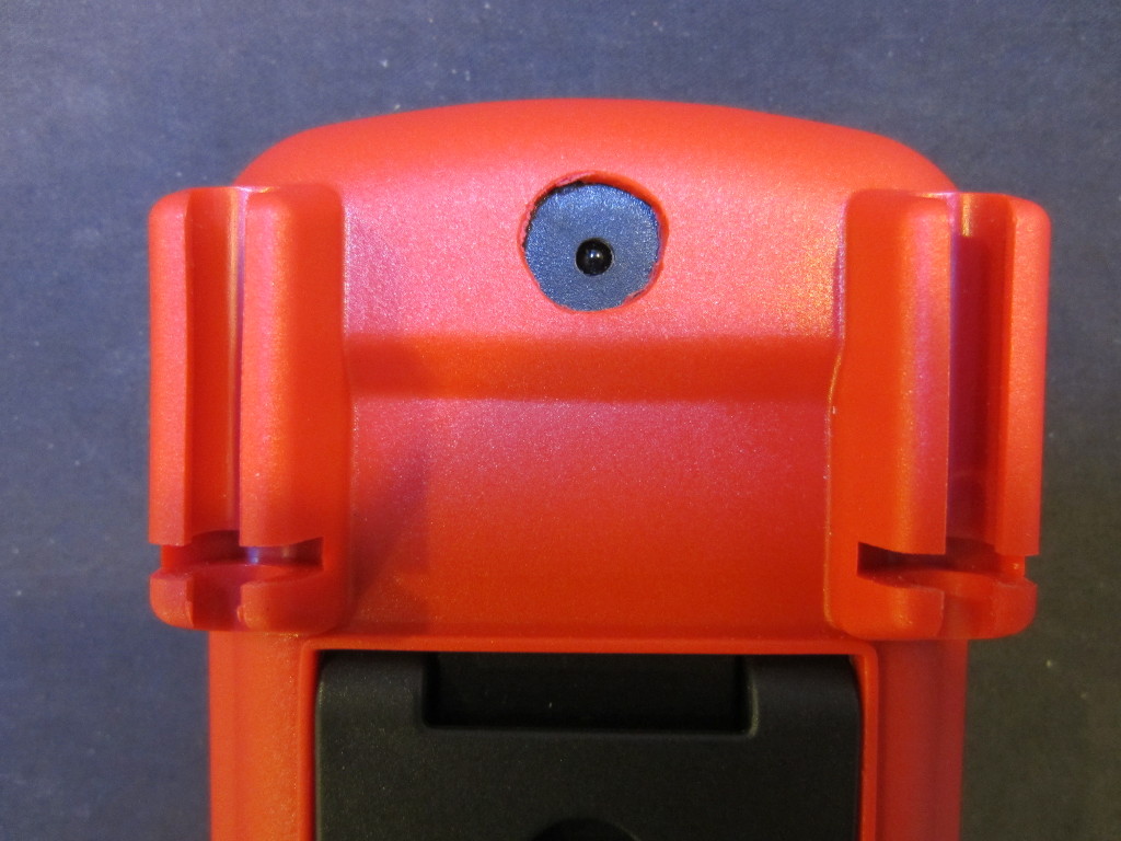
I cut a hole in the rubber holster directly over the opening where the IR emitting diode is mounted so the receiver can be connected and disconnected with ease.
|
|
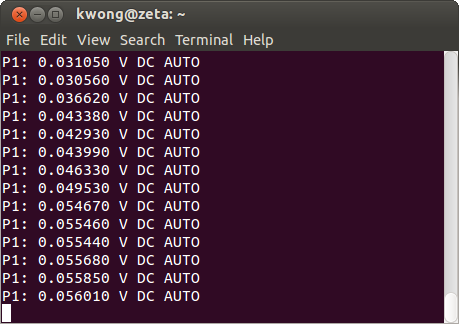
To communicate with a PC I used sigrok‘s command line utility sigrok-cli. The available driver for DTIM0660L is velleman-dvm4100. Here is the command for outputting measurement results continuously on my Linux box:
sigrok-cli --driver velleman-dvm4100:conn=/dev/ttyUSB0 --continuous
And here is a picture showing the output when the meter was set to the mV range. The output uses “V” for all voltage ranges, so the only difference among different ranges is the resolution.
Besides the above mentioned functionalities, there are many other hackable parameters (such as range switching threshold, high voltage/high current warning threshold, UART format etc.) You can take a look at the manual linked from sigrok’s site for more information. If there is enough interests, I can translate the datasheet into English and post it on my website. So if you are interested, please let me know.
Update
The translated datasheet for DTM0660 can be found here.

