ADS1224 is a 24-bit delta-sigma analog-to-digital converter with 4-channel differential inputs multiplexer. This ADC chip offers a 20-bit effective resolution (6 to 7 digits of resolution in full scale), which makes it ideal in high-resolution voltage measurement applications.
The minimum setup requires an external 2.5V voltage reference (e.g. TL431, or a higher precision 2.5V reference such as AD580), an external clock source (e.g. 2MHz) and low-pass filters on the differential input pins. Because ADS1224’s high resolution, the input filters are mandatory on the differential inputs in order to obtain stable and accurate results. The input filter from the reference design (see image below) is more than adequate in most situations:
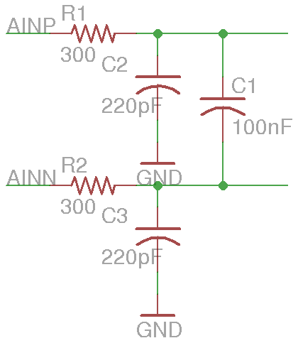
The default ADC range for each channel is ±2Vref (±5V). Resistor divider can be used to increase the measurement range. If the input voltage could go beyond the specified maximum range, other protection devices must be added to the differential inputs to prevent possible damages to the chip.
Unlike other ADC chips, ADS1224 does not use the standard SPI or I2C protocol, but uses its own serial protocol instead. Also, an external clock source is required for the ADC’s operation. ADS1224 can operate under a wide range of clock frequencies. Typically the clock speed ranges from 2MHz to 4Mhz (for simultaneous rejection of 50Hz and 60Hz noise, 910kHz clock can be used, please refer to datasheet for more details), and the conversion speed is directly affected by the system clock rate. At 2MHz, the conversion rate is about 120 SPS.
The clock required for ADS1224 can be generated conveniently using Arduino’s hardware timers. To generate the 2MHz clock using Timer0 for instance, we can configure Timer0 in fast PWM mode and use OCR0A as the counter top. Since the frequency of the fast PWM is determined by:
\[f_0 = \frac{f_{clk}}{2N(1 + OCR0A)}\]
And by default the pre-scaler N is set to 64 in Arduino, we need to set the pre-scaler to 1 and set OCR0A to 3 in order to get our desired 2MHz frequency.
Keep in mind that other timing functions that depend on the pre-scaler will need to be re-interpreted in order to get the desired results. The Serial functions are also affected although I don’t believe the baud rates are affected by the pre-scaler changes. This could have been caused by the circular buffer implementation in Arduino. Anyway, a simple way to get around this is to use the default 64 pre-scaler when debugging and change the pre-scaler back to 1 once you are satisfied with the code. You can take a look at the conditional compilation code in setupADCClock() later on to see how this is done. The only disadvantage to this approach is that with the pre-scaler set to 64 the system clock is very slow, at only 32.5 kHz. This means that during debugging the conversion rate is very slow also, and the accuracy of the results are likely affected due to the charge/discharge RC constants of the sampling capacitors.
The serial protocal ADS1224 uses is fairly straightforward to implement. Self-calibration is done by issuing at least 26 system clocks. And the reading of the ADC results is done by shifting out the 24 bit data MSB first. The DRDOUT pin (data ready/data out) serves two purposes: a transition from high to low indicates that the converted data is ready and the converted data can be shifted out by applying 24 clocks afterwards. After the data is shifted out, an additional clock will bring the line back high and the next conversion cycle begins. The conversion results are in 2’s complement, function getADCVoltageMeasurement() converts them into the signed voltage readings.
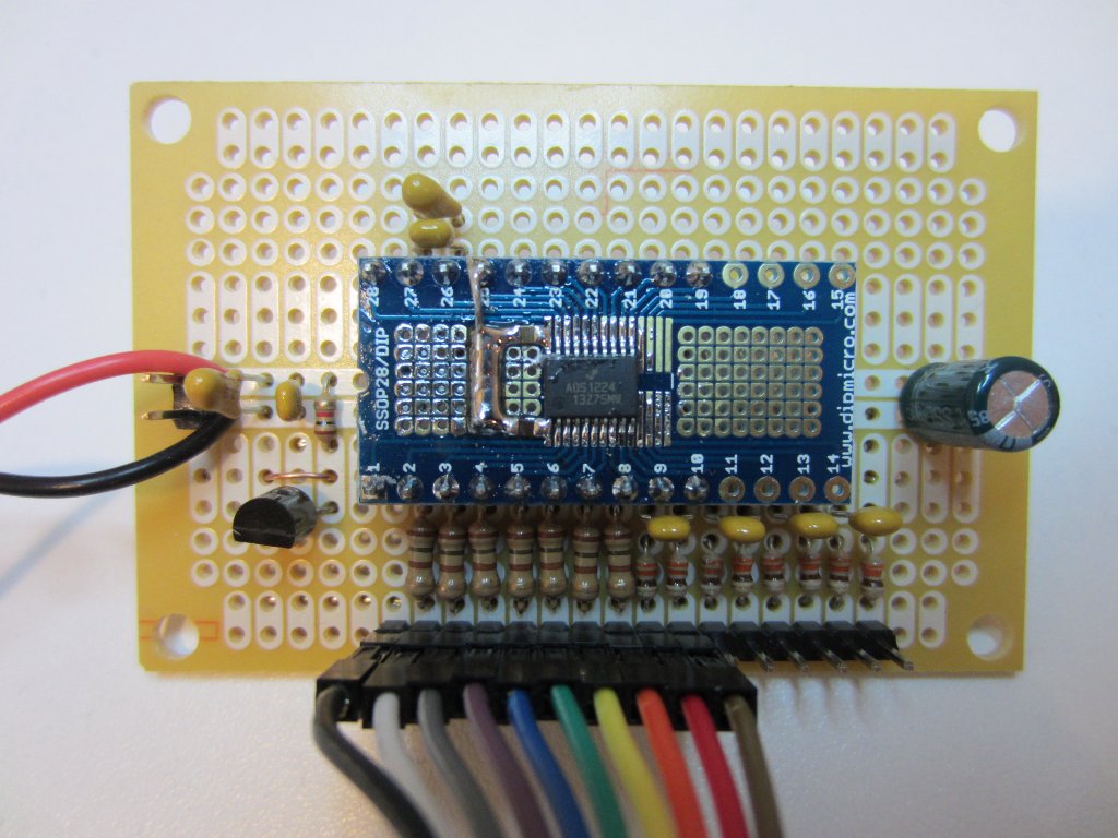
In order to achieve the maximum resolution, the datasheet has some pretty strict board layout requirements. Typically speaking, this kind of precision device is not suited for proto-boarding. In order to obtain accurate results, the bypass capacitors must be placed as close to the analog and digital Vcc pins as possible. If you take a look at the protoboard I built below, you will see that the bypassing capacitors are placed directly on the breakout board. And the ground is wired directly to the board below using a thick wire instead of relying on the small traces on the breakout board.
The following is the full Arduino code listing. You can save two pins if you are not using the built-in temperature sensor or the buffer function. In this case, you can simply tie PIN_TEMPEN and PIN_BUFEN to the ground. If you are only using a single channel, two more pins (PIN_MUX0, PIN_MUX1) can also be freed up by pre-wiring them to select the desired channel. So as a bare minimum, only three pins (PIN_SCLK, PIN_CLK and PIN_DRDOUT) are needed.
/*
 * ADS1224
 * Kerry Wong
 * http://www.kerrywong.com
 * 12/2012
 */

//uncomment the following line when debugging
//#define DEBUG 1

const int PIN_SCLK = 7;
const int PIN_CLK = 6;
const int PIN_DRDOUT = 4;
const int PIN_MUX0 = 3;
const int PIN_MUX1 = 2;
const int PIN_TEMPEN = 9;
const int PIN_BUFEN = 8;

/*
 * Setup 2MHz CLK on PIN_CLK
 * using Timer 0
 * Pin 6 (PIN_CLK)
 */
void setupADCClock()
{
    //set TOP of the comparator register
    OCR0A = 3;

    //Fast PWM, OCR0A top
    //COM0A1 COM0A0 COM0B1 COM0B0 - - WGM01 WGM00
    //  0       1     1       0   0 0   1     1
    //TCCR0A = 0x63;
    TCCR0A = _BV(COM0A0) | _BV(COM0B1) | _BV(WGM01) | _BV(WGM00);

    //No prescaling
    //FOC0A FOC0B - - WGM02 CS02 CS01 CS00
    //                  1    0     0    1
    //f = fclk/(2*N*(1 + OCR0A))
    //  = 16/(2*1*(1 + 3))
    //  = 2 MHz
    //in DEBUG mode
    //f = 16/(2*64*(1+3))
    //f = 31.25 KHz
#ifndef DEBUG
    // clear the prescaler bits
    // only when DEBUG is not set
    TCCR0B &= 0xF0;
#endif
    //TCCR0B |= 0x9;
    TCCR0B |= _BV(WGM02) | _BV(CS00); //set prescaler to 1
}

/*
 * Send clocks for the number of cycles specified
 */
void sendClock(int cycles)
{
    for (int i = 0; i < cycles; i++) {
        digitalWrite(PIN_SCLK, HIGH);
        digitalWrite(PIN_SCLK, LOW);
    }
}

/*
 * Get the raw converted data
 */
unsigned long getADCResult()
{
    unsigned long r = 0;

    //wait till the conversion is done
    while (digitalRead(PIN_DRDOUT) == HIGH);

    //shift out the 24 bits data
    for (int i = 0; i < 24; i++) {
        digitalWrite(PIN_SCLK, HIGH);
        delayMicroseconds(1);
        digitalWrite(PIN_SCLK, LOW);

        r |= digitalRead(PIN_DRDOUT);
        if (i!= 23) r = r << 1;
    }

    //one extra CLOCK to bring DR pin high
    digitalWrite(PIN_SCLK, HIGH);
    digitalWrite(PIN_SCLK, LOW);

    return r;
}

/*
 * select the current ADC channel
 * chn: 1 .. 4
 */
void selectADCChannel(int chn)
{
    switch (chn)
    {
    case 1:
        digitalWrite(PIN_MUX0, LOW);
        digitalWrite(PIN_MUX1, LOW);
        break;
    case 2:
        digitalWrite(PIN_MUX0, HIGH);
        digitalWrite(PIN_MUX1, LOW);
        break;
    case 3:
        digitalWrite(PIN_MUX0, LOW);
        digitalWrite(PIN_MUX1, HIGH);
        break;
    case 4:
        digitalWrite(PIN_MUX0, HIGH);
        digitalWrite(PIN_MUX1, HIGH);
        break;
    }
}

void initADC()
{
    pinMode(PIN_SCLK, OUTPUT);
    pinMode(PIN_CLK, OUTPUT);
    pinMode(PIN_DRDOUT, INPUT);
    pinMode(PIN_MUX0, OUTPUT);
    pinMode(PIN_MUX1, OUTPUT);
    pinMode(PIN_TEMPEN, OUTPUT);
    pinMode(PIN_BUFEN, OUTPUT);

    setupADCClock();

    digitalWrite(PIN_SCLK, LOW);
    digitalWrite(PIN_DRDOUT, HIGH);

    //self-cal
    sendClock(26);

    //disable temperature measurement
    digitalWrite(PIN_TEMPEN, LOW);

    //disable input buffer
    digitalWrite(PIN_BUFEN, LOW);
}

/*
 * Get the voltage measurement
 */
double getADCVoltageMeasurement()
{
    unsigned long r = getADCResult();
    double v;

    // convert 2's complement
    // if r > 2^63, it's negative
    // Vref = 2.5V
    if (r >= 8388608.0) {
        v = (double)(r - 16777216.0)/8388607.0*5.0;
    }
    else {
        v = (double) r / 8388607.0*5.0;
    }

    return v;
}

void setup()
{
    //Note, Serial will only work when
    //in DEBUG mode
    Serial.begin(9600);

    initADC();
    selectADCChannel(4);
}

void loop()
{
    unsigned long r = getADCResult();
    double v = getADCVoltageMeasurement();

    Serial.print(r);
    Serial.print(" --- ");
    Serial.println(v,5);
}

