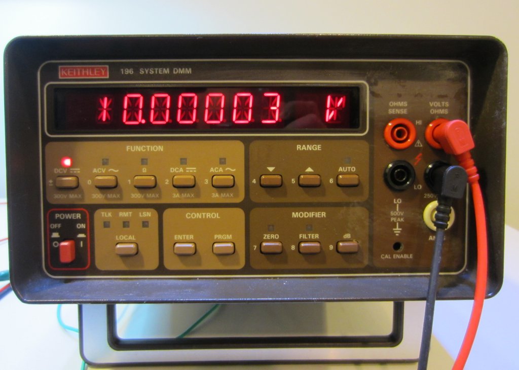
I bought a used Keithley 196 bench multimeter a few weeks ago. This is a 6 ½ digit 3,030,000 counts meter, capable of measuring voltages down to 100nV and currents as low as 100nA. It can also be used to measure low resistance with a resolution of 100 µΩ using 4-wire measurement. And because of the high input resistance on lower voltage ranges (> 1 GΩ), this meter is great for working with analog circuits where precision measurements are often required.
While the unit I received was last calibrated many years ago, it remained to be well in spec. The picture below shows the 10V DC voltage reading using a voltage standard.
 |
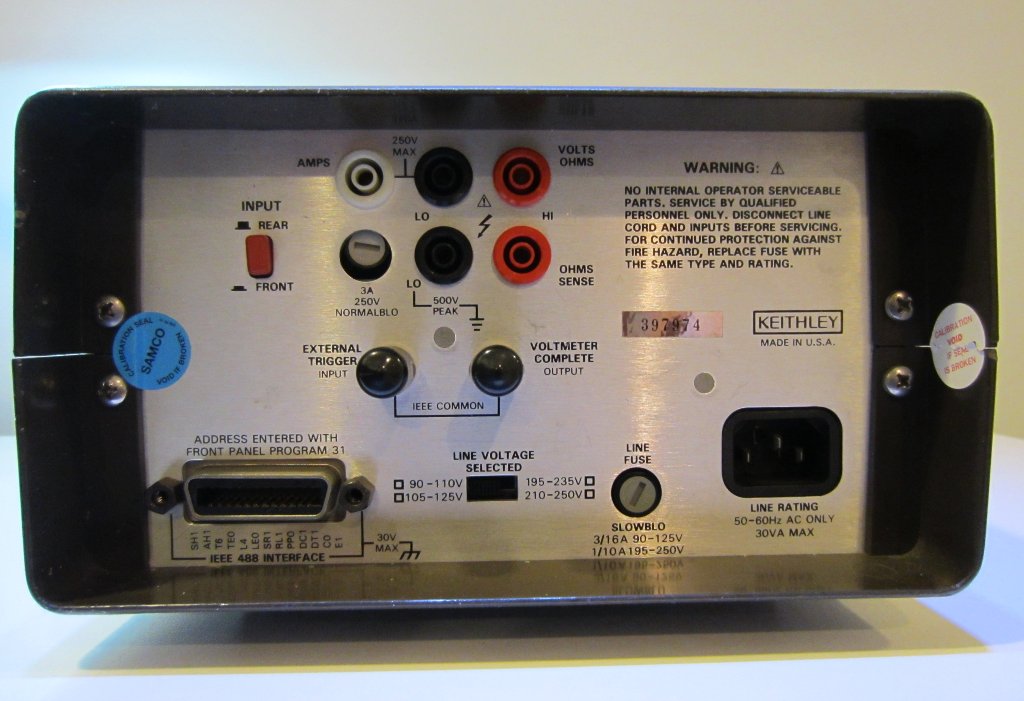 |
Like many instruments made back in the days, Keithley 196 has its firmware stored in EPROMs (27128). The calibration data is stored in a small on-board EEPROM (KM2816A). While the reliability of EPROMs and EEPROMs are typically quite good, the real world data is still few and far between. Most manufactures guarantee at least 10 years data retention period for EPROMS and EEPROMS (some newer EEPROMs like this one have a guaranteed retention period of more than 200 years) but under typical operation conditions the data retention period is likely to be magnitudes longer. Since Keithley 196 is considered obsolete by the manufacturer, it might be hard to get a hold of the firmware should the EPROM fail however. So I decided to backup the firmware along with the calibration data just in case.
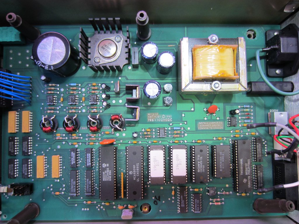
The EPROM and EEPROM chips are located on the main board, which according to the service manual lies underneath the analog circuit board. The picture below shows the Keithley 196 with the top cover removed.
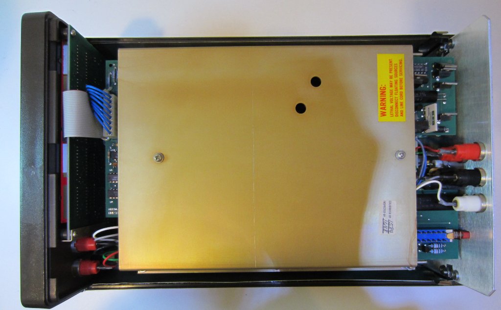
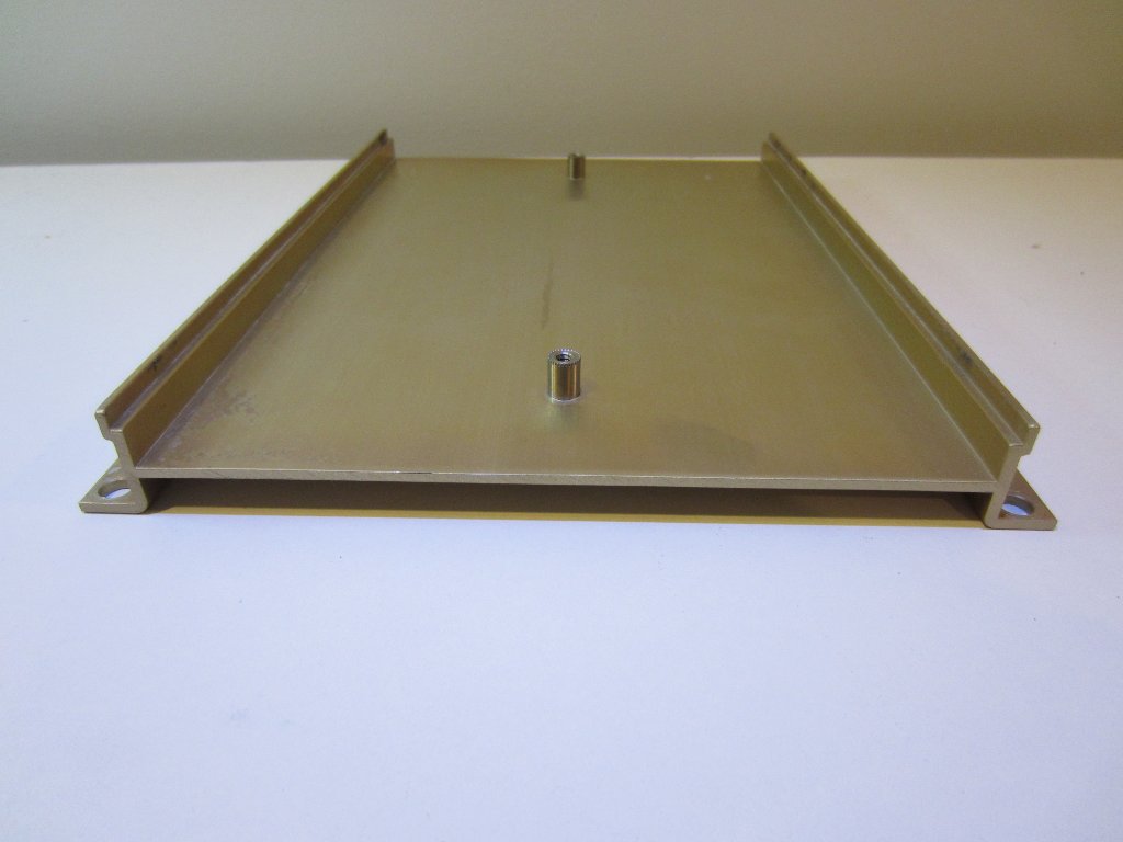
The top analog circuit board is encased between two pieces of very thick aluminum shielding, and the bottom piece serves as the mounting plate for the analog board as well.
 |
 |
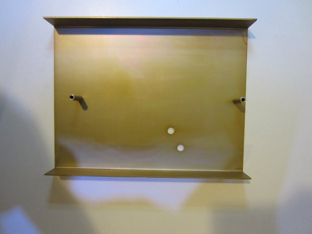
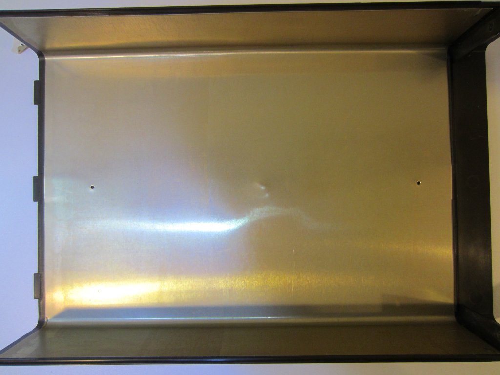
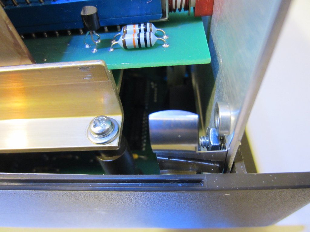
The pictures below show the shielding attached to the inner wall of the instrument cover which provides additional shielding. The cover is grounded through contact with the metal clips on the lower half of the case. The seemingly excessive shielding is necessary for preventing environmental electromagnetic field interfering with the precision analog circuit. Even with this level of shielding, the manual still suggests placing the meter away from other instruments and interference sources.
 |
 |
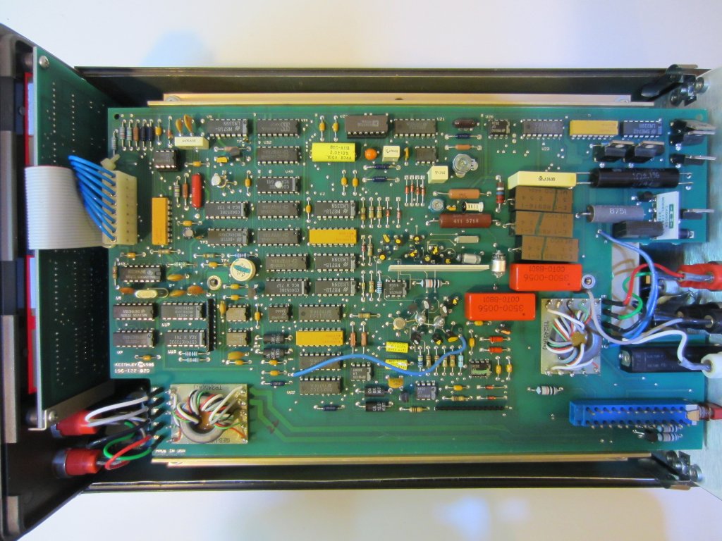
The pictures below are the top analog circuit board and the main board at the bottom, with the shielding and analog board removed:
 |
 |
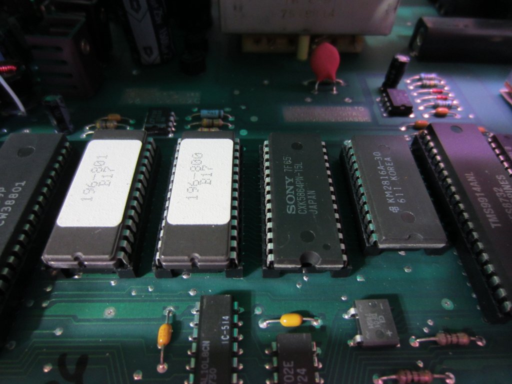
The two EPROM chips where the firmware is stored can be easily identified on the main circuit board (marked 196-800 B17 and 196-801 B17 respectively). The chip to the right of the EPROMs (marked KM2816A-30) is the EEPROM where the calibration information is stored. All these chips are socketed so it is pretty trivial to remove them.
These three chips are parallel memory chips so it is pretty straight forward to dump the content.
I used an Arduino to retrieve the stored information. Because ATmega328 does not have enough pins for all the address/data lines, I used a 16-bit SPI port expander MCP23S17 to handle the address lines and use the I/O pins from Arduino to handle the data output. Of course, you can use pretty much any micro-controllers that you are familiar with as long as TTL logic levels are supported. The code I used can be downloaded towards the end.
Here is a picture of my setup:
 |
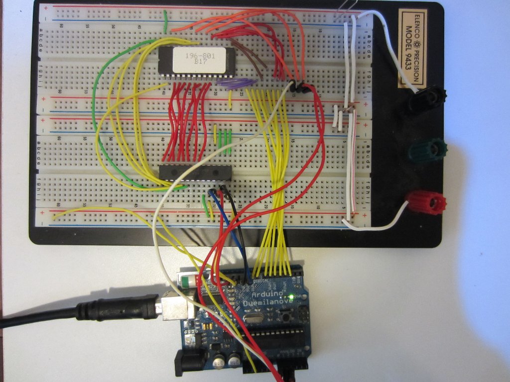 |
Both 2718 and 2816 can be read using the same circuit setup. The pinouts of these two chips are quite similar. When the chips are right aligned on the breadboard, the lower address pins and data pins will all line up correctly. The only exception is the Write Enable (WE) pin, which are located at different positions on each chip.
Since we are reading the chip content only, it is a good idea to tie WE to VCC directly. This will prevent the possibility of accidental writes to the EEPROM chip when dumping the data (for the EPROM, this is less of a concern as a high programming voltage is required for writes). You can download the firmware along with the calibration data using the links at the end.
According to the service manual, you should only flash the same version of the firmware as what is currently on your instrument. Also, the calibration data is device specific so do not attempt to flash your calibration EEPROM with data obtained elsewhere. It is only useful in situations where the EEPROM is corrupted and you wanted to ensure that the EEPROM is restored to a known state prior to re-calibration.
Keithley 196 firmware (version B17)
Keithley 196 calibration data

