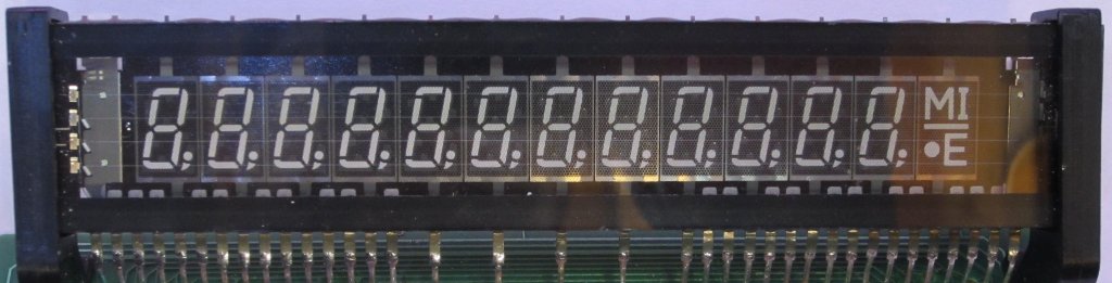
I recently salvaged a vacuum fluorescent display (VFD) from a piece of old test gear. The VFD is a 13 digit 7-segment multiplexed display and I thought it would look great in a custom digital clock or something similar. While it has the model number FUTABA 13-MT-54NA, I could not find any information on the internet specifically for this model.
Of course, before I could put this vacuum fluorescent display to use in my final project, I needed to first build a driver circuit to drive this display. Unlike driving a multi-digit 7-segment LED display, driving a VFD is a little bit more complex due to the multiple voltages involved and the relative potential requirement for the filament. Of course there are many specialized chips we could use to build a VFD driver with, but like with many of my previous projects I love to build things from scratch so I thought I would build the filament driver and the VFD driver myself.
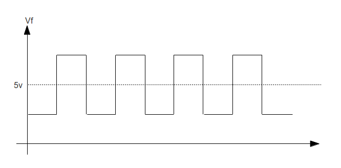
One of the key design considerations for the filament driver is the need to “float” the filament potential above the ground. This offset voltage is necessary to prevent ghosting (see this app note for more detailed explanation). Also in order for the illumination to be uniform, an AC drive current waveform from a center-tapped transformer is desired. A typical filament driving waveform is illustrated below:
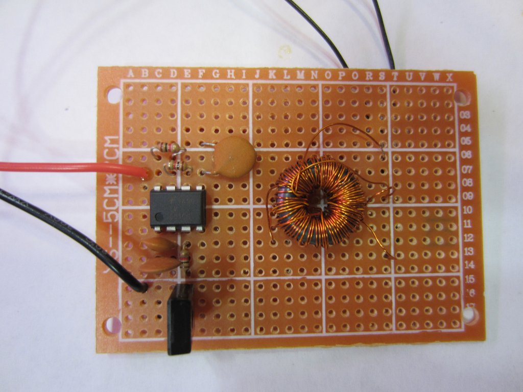
Fortunately, we can generate this waveform by biasing the center tap of a pulse transformer above the ground and feeding a square wave through it. The following circuit design shows such a filament driver circuit using a 555 timer and a center-tapped transformer. The 555 timer is configured as an astable oscillator. Given the RC values chosen (1k, 4.7n), the operating frequency is right around 100 kHz. The diode across R1 ensures that the output waveform from pin 3 has a 50% duty cycle.
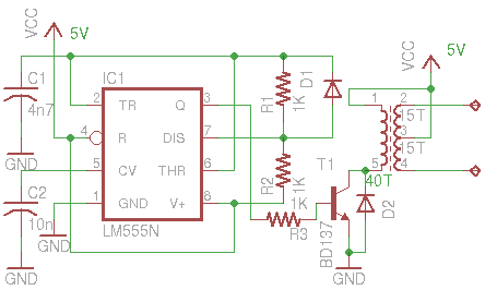
The pulse transformer was hand-wound using a torroid core. Because the operating frequency is relatively high, only a few turns are needed for each winding as a result. In my case, I used 40 turns for the primary winding and two 15~20 turns for the secondary (depending on the voltage required for the filament). Using the values given, the measured RMS voltage across the filament is at around 2.2V.
Because the center tap is tied to +5V, the filament potential will stay above ground level at all times and thus preventing electrons reaching the anode when the grid voltage is 0. This in turn eliminates the ghosting effect.
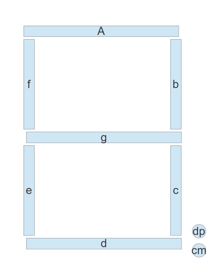
Figuring out the actual pinout of the module is relatively easy. Since I couldn’t find it anywhere, I thought I would share the pinout information here.

Also see A DIY Vacuum Fluorescent Display Driver.

