Arduino‘s (ATmega328P) PWM outputs via analogWrite can be conveniently turned into analog voltage levels through the use of simple RC filters. Since the PWM outputs are not isolated, using them to drive other devices directly could be potentially dangerous. This is especially true if the target circuit uses a higher supply voltage.
Fortunately, it is quite easy to isolate the PWM output using an optocoupler. The following schematic shows how we can build such a fully isolated DAC:
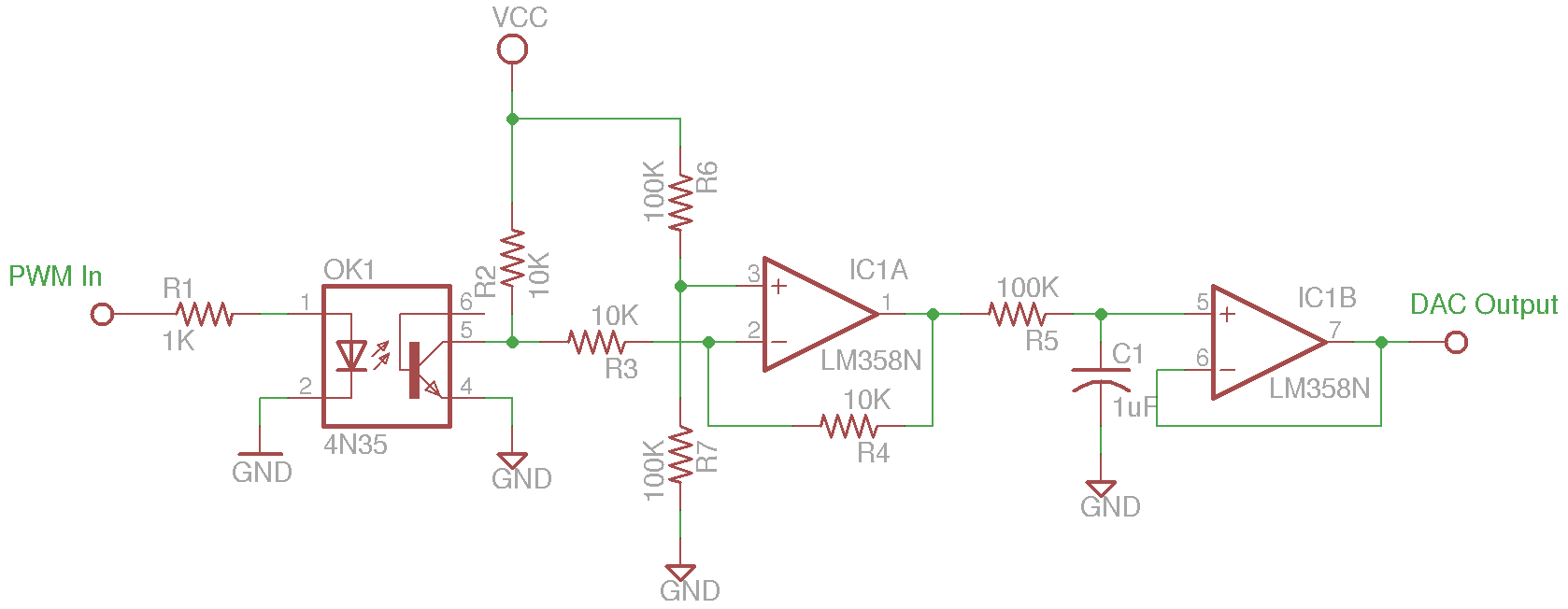
The PWM output pin from the MCU drives the emitter side of the optocoupler. Most MCU output pins can deliver at least a few mA current so driving an optocoupler directly via a current limiting resistor should not be an issue. In my implementation, a 4N35 optocoupler is used, but you can pretty much use any optocouplers.
The output waveform from 4N35 is inverted with regard to the input as the optotransistor within 4N35 operates like an inverter. The inverted PWM signal is flipped once again through the unity gain inverting amplifier. An RC low-pass filter (R5 and C1) turns the PWM output into DC voltage and finally this DC voltage is buffered through a voltage follower to the output. The RC constant needs to be chosen so that it is significantly larger than the PWM interval. The PWM frequency via Arduino’s analogWrite is roughly 490 Hz (roughly a 2 ms cycle), and the RC constant in the example above is 100 ms, which is sufficiently large to guarantee a smooth output. Note that the circuits on either side of the optocoupler do not have to share the ground reference as illustrated in the schematics above.
I used LM358 as the OpAmp. Since LM358 is not a rail-to-rail OpAmp, the DAC output range is going to be limited by the supply rail. If your application requires higher accuracy, you could either use a rail-to-rail OpAmp or use a slightly higher voltage dual supply rail to power the OpAmp.

