A while back, I wrote an article on how to use a CP2102 USB/UART converter chip in place of an FT232RL to program an ATmega328P using Arduino bootloader. Of course, not everyone has the time or wants to build one from scratch. And since CP2102 is offered in QFN package only, it is a big pain to solder without a proper adapter board and decent soldering equipment.
Fortunately, there are a lot of CP2102 based cheap USB/UART adapters on the market. If you search on eBay, you will find quite a few different kinds of USB/UART boards based on CP2102. The cheapest ones cost only a couple of bucks each, making them great alternatives to the FT232 based USB/UART converters. You need to careful however when choosing a CP2102 adapter, since not all CP2102 module boards have the DTR (Data Terminal Ready) pin required by Arduino (if you are using the Arduino bootloader). But, even if the module does not have a pinout for DTR, you can easily modify it to make the board compatible with Arduino.
The following is a picture of one such CP2102 board:
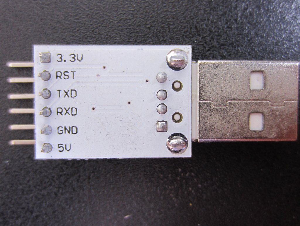
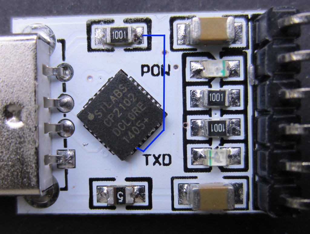
To make it work with the Arduino bootloader, one easy approach is to disconnect the RST header pin from CP2102 pin 9 and connect it to the DTR pin (pin 28) instead. While in the Arduino schematics, the reset pin is connected to the ATmega328P pin 1 (RST) via a 100 ohm resistor, this connection is not strictly needed as pulses from the DTR pin (connected to ATmega328P pin 1 via a 100nF capacitor) will reset the MCU properly during programming. The two pictures below illustrate the connection between the module RST header and the RST pin of CP2102.
|
|
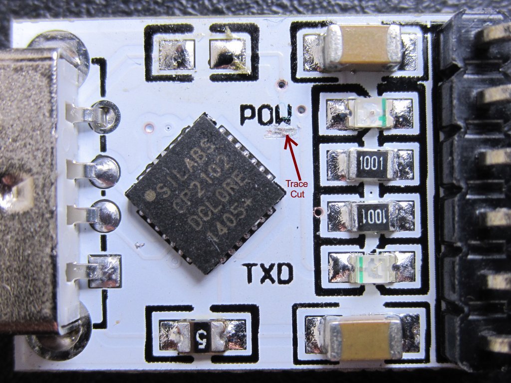
Because the module RST pin header is connected to the 100 Ohm resistor, the resistor needs to be desoldered first to free up the reset pin connection. Once the resistor is desoldered, we can cut the trace between the 100 Ohm resistor and CP2012 pin 1 (the trace is highlighted in blue in the picture above) so the right side of the pad where the 100 Ohm resistor once occupied is not connected to anything but the reset pin header.
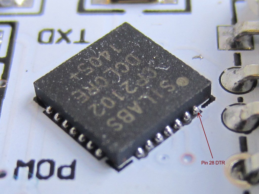
Now we can solder a jumper wire between the pad and pin 28 of CP2102. Because CP2102 is a leadless chip, we technically are not soldering the wire onto its pad directly, but are joining the wire with the excessive solder on the PCB pad. This might be a bit tricky to accomplish, but since the DTR pin is located towards the edge of the chip, the soldering is not extremely difficult and can be done relatively with ease using a fine tip soldering iron.
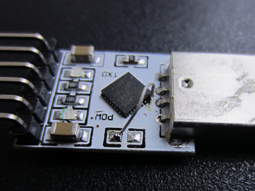
Once the DTR pin is connected to the header, this CP2102 module can be used to program an Arduino bootloaded ATmega328p chip using the Arduino IDE by connecting the DTR (labeled Reset) pin to ATmega328P pin 1 (RST) via a 100nF capacitor, the TX pin to the MCU RX pin (pin 2) and the RX pin to the MCU TX pin (pin 3). For more information, please see my previous posting on using CP2102 with Arduino.

