MCP3903 is a six channel Delta-Sigma A/D converter. It features six synchronous sampling differential channels which can be programmed to sample between 16 bit and 24 bit accuracy, the gain for each channel can also be programmatically set from 1 up to 32. It also has an internal low tempco (5ppm/°C) voltage reference, making MCP3903 an excellent choice for digitizing small differential signals from various sensors.
I have created a library for Arduino. It allows you to explore most of the functionalities MCP3903 provides with ease. The library can be downloaded towards the end of this post as usual. And it is also available on GitHub.
MCP3903 communicates with MCU over SPI and for the most part, the communication is pretty straight forward. Unlike many SPI devices for which the sending and receiving of the data happen simultaneously during an SPI.transfer call, sending and receiving data are done in MCP3903 via different commands. In its simplest terms (which covers most of the scenario), the communication (either sending or receiving) packet includes four bytes. The first byte is the control byte, which contains the device address, the register needs to be accessed and whether this command is a read or write. The subsequent three bytes are either read from or send to MCP3903 depending on whether the command is a read or write.
This fixed-width command structure makes programming very easy. For different ADC resolutions (e.g. 16 bit versus 24 bit) the command and data structures are identical. The ADC result would always contain 24 bits, the lower bits are simply filled with zeros when the resolution used is less than 24 bits. Again, this makes programming a lot simpler as we can treat all conversion results as 24 bits regardless of the resolution used.
Of course, when using some special features (e.g. continuous read), the command structure is slightly different than what we have mentioned above, but you can always add in these functions if you want to use them. But 90% of the time the functionalities provided in this library should be sufficient.
There are a couple of things you will need to pay attention to when using MCP3903. First, voltages applied at each differential pairs are limited to ±0.5V (when using a gain of one). While each of the analog inputs can handle up to ±6V without suffering any damage, the measurement results will not be accurate when the voltages fall outside of the linearity range. Second, MCP3903 has a gain of 3 amplifier on each channel, which is independent of the programmable gain settings. If you take a look at the implementation of the library function readADC, you will notice that the result has been scaled down by a factor of 3 to reflect the original measurement value.
Below are a few most used functions. For the full implementation, please refer to the source code linked towards the end of this post.
reset
This function resets MCP3903 to 24 bit operation mode (when no parameter is supplied), or you may specify a predefined OSR (over sampling ratio) factor for the desired bit resolution. Note that the reset does not change other register settings except for the gain setting mentioned earlier. According to the datasheet, a full reset can only be achieved via the RESET pin (pin 27).
setGain
This function changes the gain setting for the given channel. It can take either two parameters or three parameters. When two parameters are supplied, the first parameter is the channel number (0-5), and the second parameter is the desired gain (GAIN_1, GAIN_2, GAIN_4, GAIN_8, GAIN_16, GAIN_32 and GAIN_64). When a third parameter is supplied, the last parameter indicates whether to turn on current boost mode for the channel (1 to turn on boost).
readADC
Returns normalized ([-1,1]) ADC data for the supplied channel. Multiply this result by the reference voltage will yield the measured voltage. Because the value for the internal high stability (5ppm/°C) voltage reference can vary up to ±2%, you will want to measure the reference output with a high precision meter to obtain the reference voltage for your particular ADC first rather than relying on the nominal value to achieve the most accurate result. The nominal value for the internal voltage reference is 2.35V (in my example below, the actual reference voltage is 2.36V).
The following code shows how to read channel 1 results with 24 bit resolution and use a gain of 8. As mentioned earlier, the OSR_256 parameter can be omitted in this case as it is equivalent to the default reset with no parameter.
#include "MCP3903.h"
#include <SPI.h>

MCP3903 mcp3903;

void setup()
{
    SPI.begin();
    Serial.begin(9600);

    mcp3903.reset(MCP3903::OSR_256);
    mcp3903.setGain(1,MCP3903::GAIN_8);
}

void loop()
{
    Serial.println(mcp3903.readADC(1) * 2.36 , 4);
    delay(100);
}
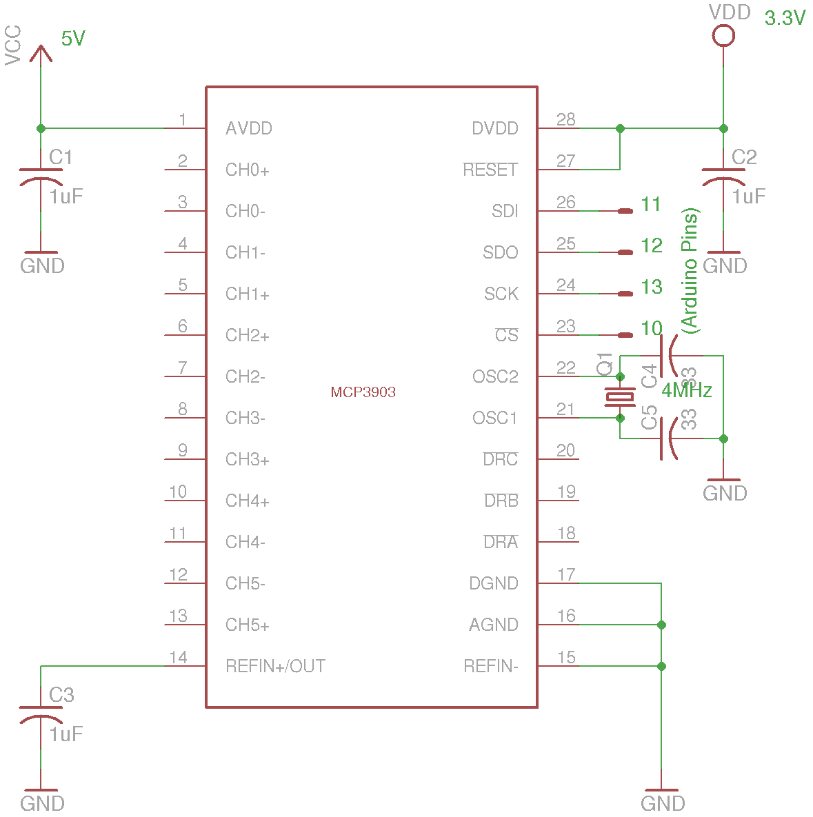
A few features are left out from this library (e.g. phase delay compensation between each pair of channels, pre-scaler settings, continuous read, etc.), but those who are interested can consult the datasheet and add in easily. The schematic below is the recommended design using internal voltage reference, note that the supply voltage for the digital portion of the circuitry is different from the analog portion. According to the datasheet, AVdd should be between 4.5V and 5.5V and DVdd should be between 2.7V and 3.6V.
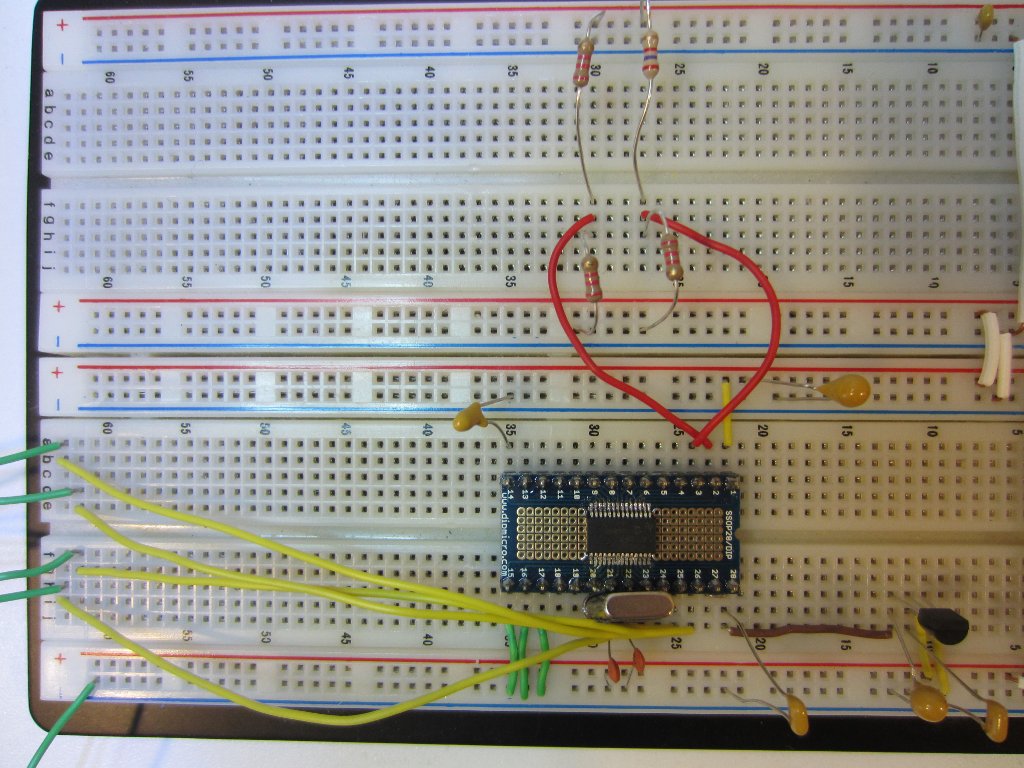
Here is a picture of my test setup. In the picture below, a small differential voltage is applied to channel 0 via a resistor bridge.