My workplace was throwing away an old SMART UF-55 DLP projector. The projector had many stuck mirrors and the lamp had already surpassed the rated useful life span. I had always wanted to take a look at a DMD chip so I decided to take it home and do a detailed teardown. You can find my video of this teardown towards the end of the post.
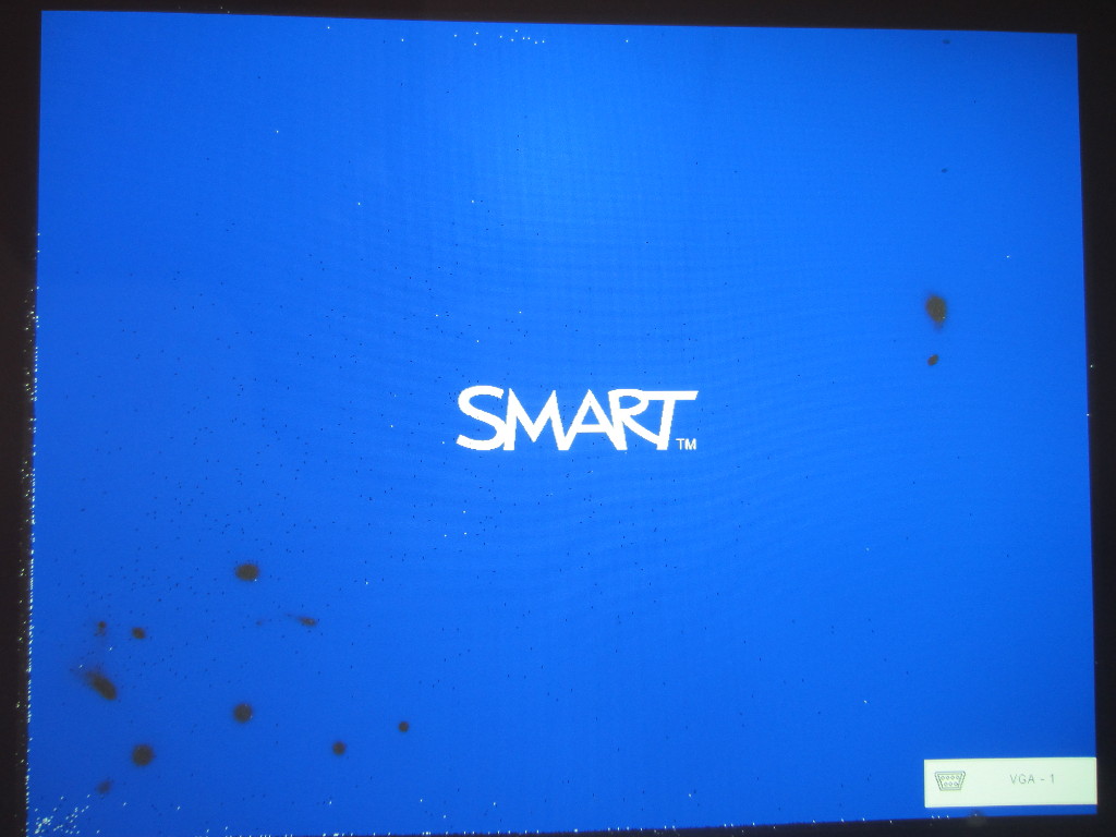
Here are a couple of screen outputs upon powering up. As you can see, the DMD chip is clearly defective.
|

|
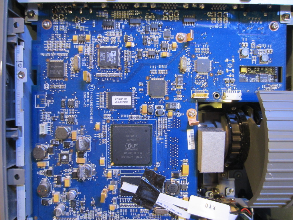
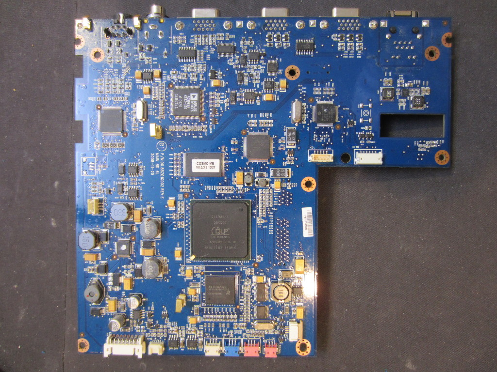
The pictures below are the main digital board.
|
|
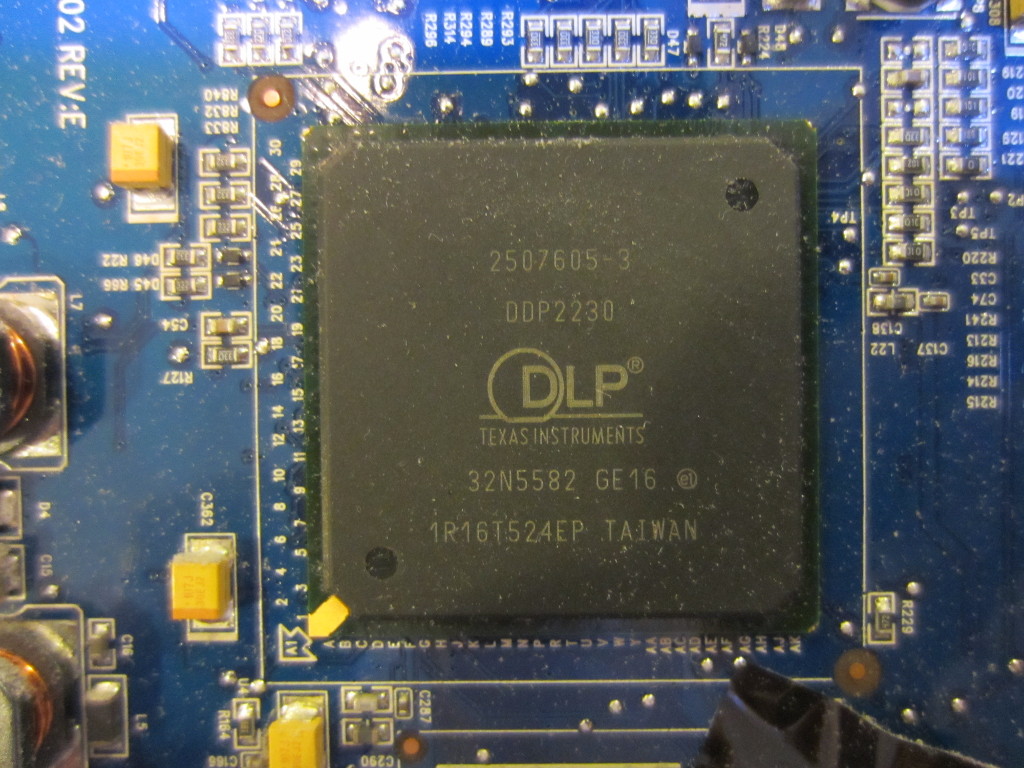
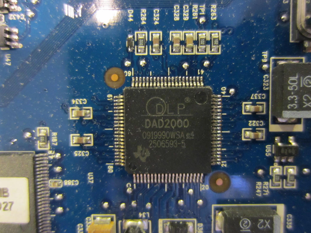
There are a couple of TI‘s DLP proprietary chips (possibly CPLD or FPGA).
|
|
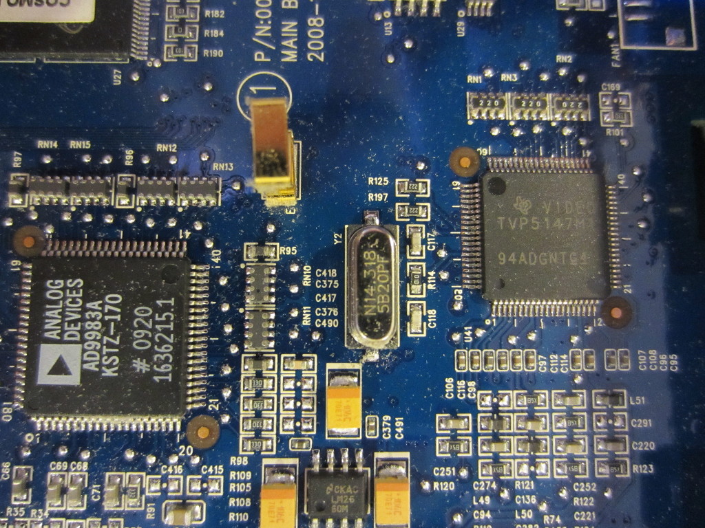
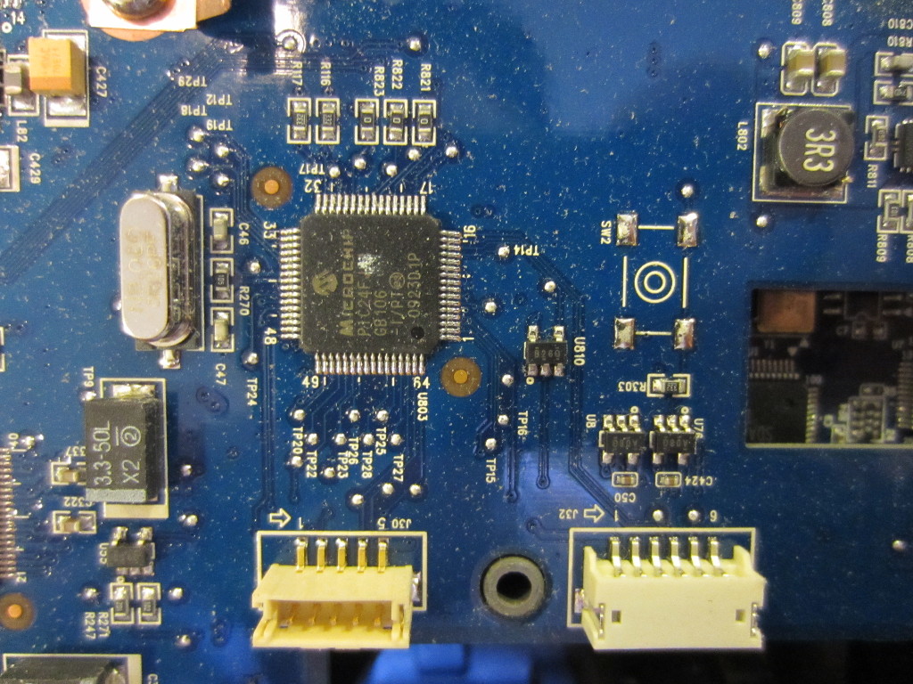
In the picture on the left below, you can find an AD9983A 8-Bit display interface IC and a TVP5147M1 10-Bit digital video decoder. In the picture to the right, you can see a PIC24FJ64 16-bit microcontroller.
|
|
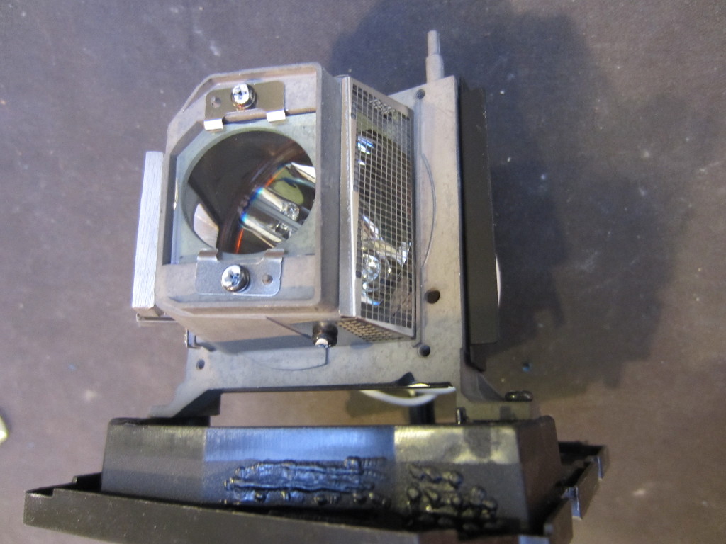
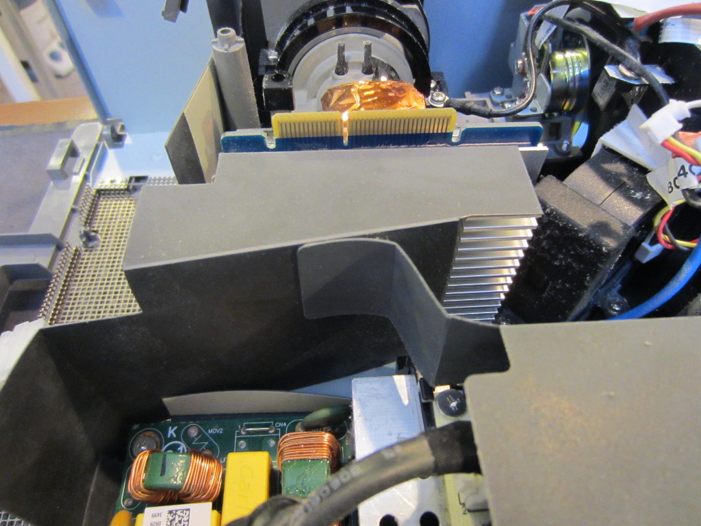
Here you can see the lamp assembly. The lamp used is some kind of metal-halide lamp. Like all discharge lamps, the lamp is started by applying a high voltage across the electrodes and once the lamp is ballasted the voltage drops while a high current is sustained. In the picture to the right, you can see the heatsink attached to the DMD assembly.
|
|
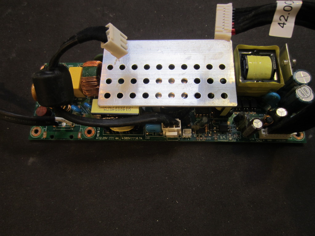
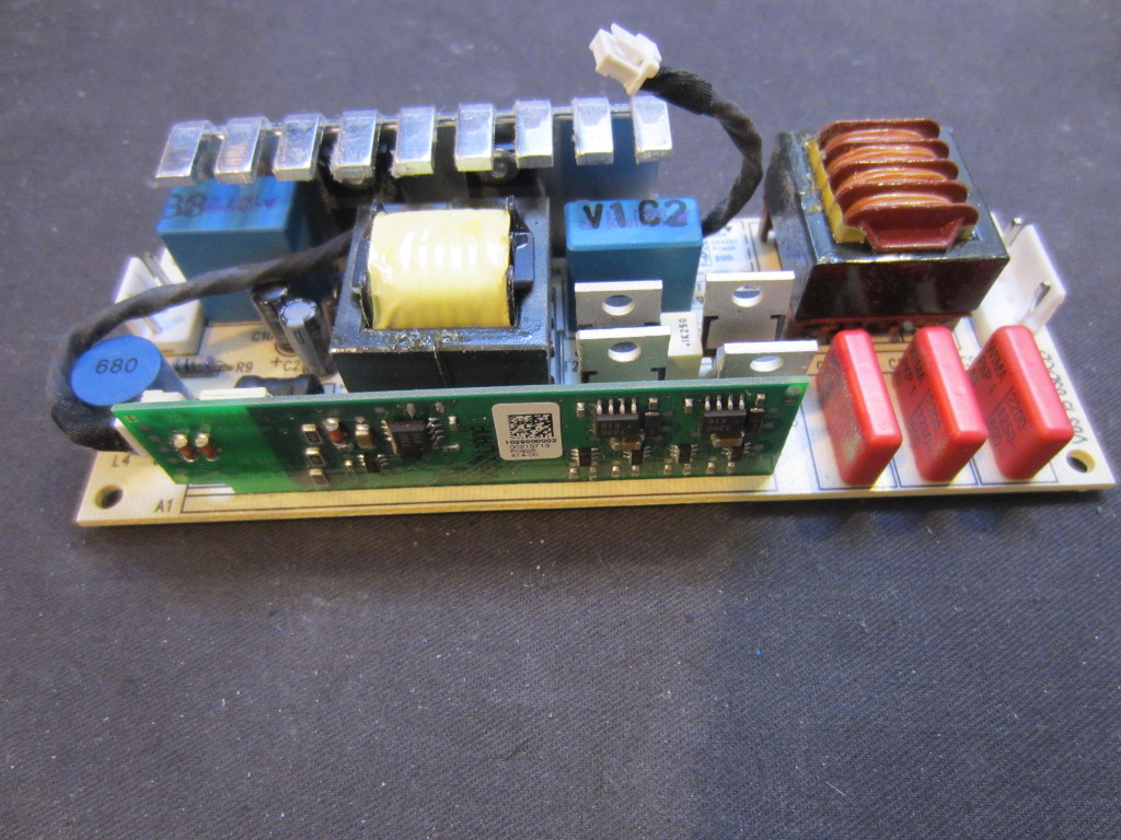
Here are the switching power supply module (on the left) and the high voltage power supply (the ballast for the lamp) respectively.
|
|
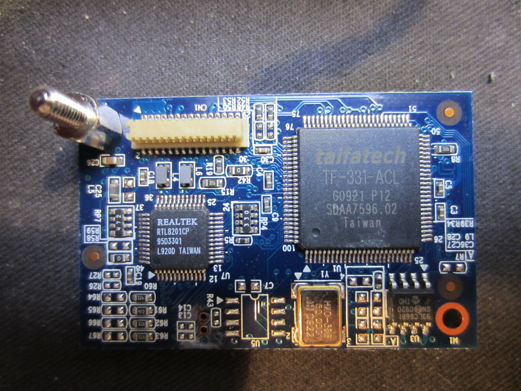
The Ethernet and LAN management are handled by a separate board. There are three boards (the main board, video/audio input/output board and the Ethernet board) which are all connected together via board-to-board connectors instead of ribbon cables. The Eithernet controller used is a RealTek RTL8201CP. The LAN management chip used here is a Taifatech TF331.
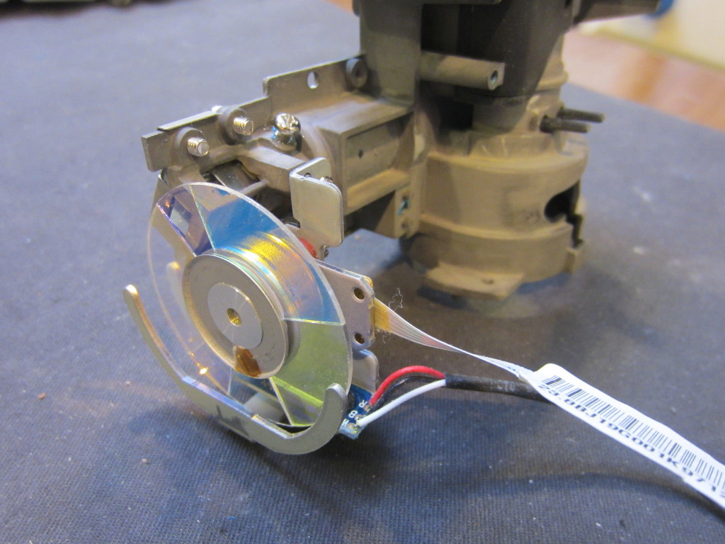
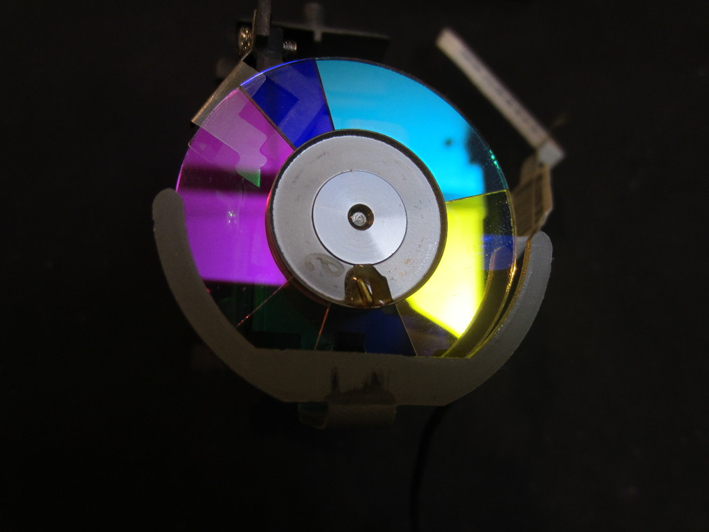
Perhaps one of the most interesting piece in side of any DLP projectors is the color wheel. Because the micromirrors inside the MDM chip can only reflect the light generated by the discharge lamp and cannot change the wavelength, color images must be generated by displaying multiple frames of monochromatic images in quick succession. Because of our persistence of vision, these images of different colors appear to be superimposed and thus what we see appeared to be colored instead of multiple monochromatic ones. So, in DLP projectors, the DMD is synchronized with the rotation of the color wheel to ensure the correct representation of colors for a given scene frame.
|
|
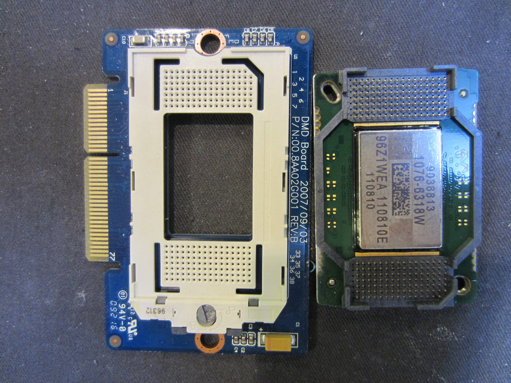
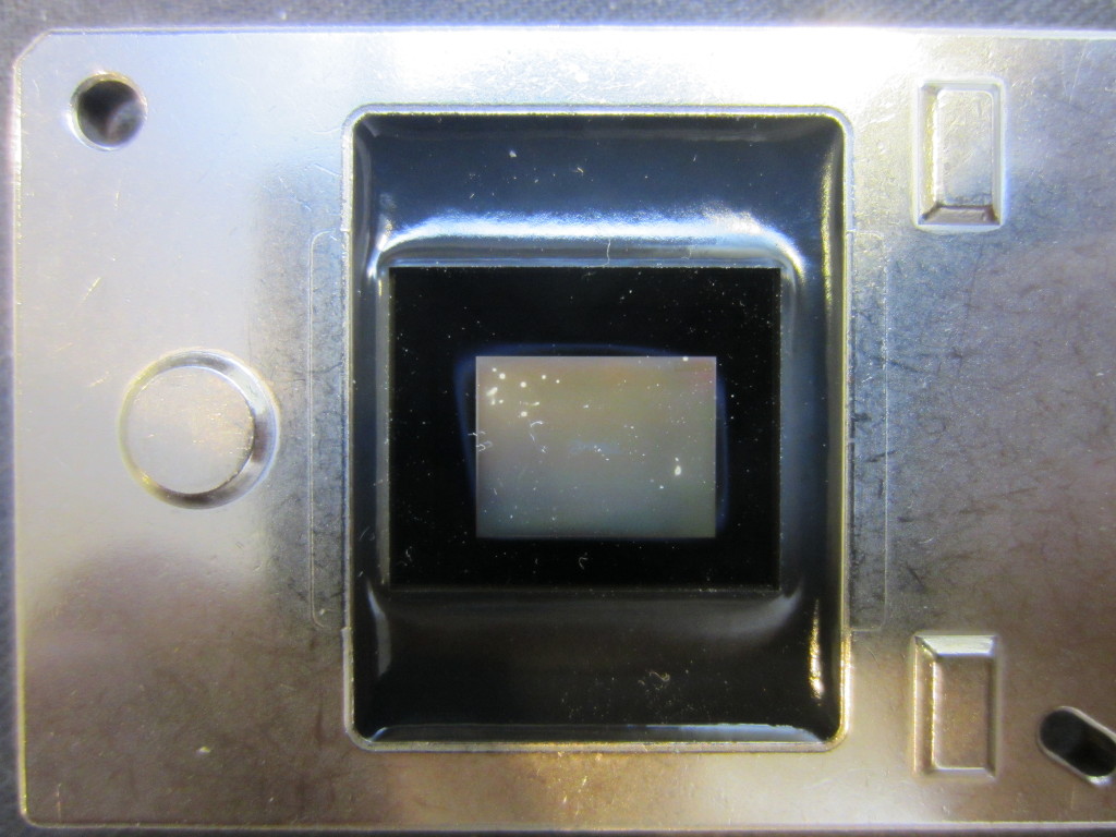
At the heart of the DLP projector is the digital micromirror device (DMD), which consist of hundreds of thousands of micromirrors depending on the specified resolution. Each micromirror is responsible for representing a single pixel on the screen. Like all micromirror devices, one of the leading causes of failure is stucked mirrors. The pixelated black dots you saw earlier on the projected screen is due to these malfunctioning mirrors.
The DMD inside this projector had some other issues. There appeared to be some deposits on the inner side of the glass screen on top of the chip. You can see this on the picture below. I am not sure what caused this, but it could be some imperfection during the manufacturing process and the loose material got deposited on the glass during operation as the temperature can get very high.
|
|
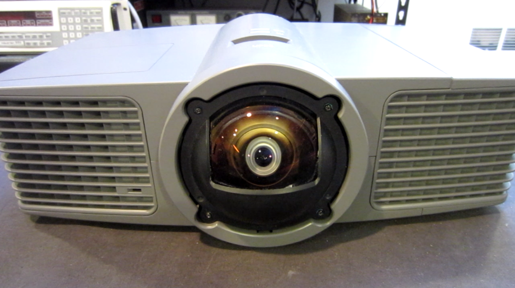
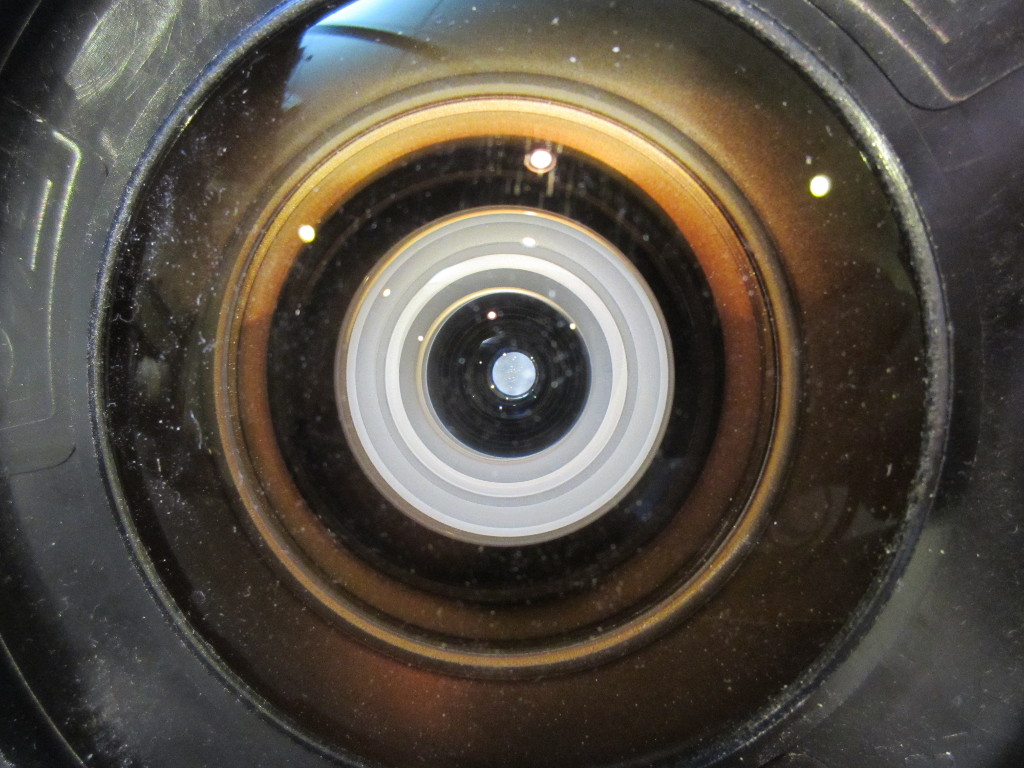
And here is a closeup picture of the main projection lens.
Finally, here is the video of this teardown:

