I bought a non-working Lambda LQ-521 linear power supply on eBay a couple of weeks ago. Usually I avoid knowingly buying something that is broken unless I am certain that I could obtain parts for it at a reasonable price. But buying broken linear power supplies is another story as most of the problem can be fixed with readily available components.
The Lamba LQ series (manufactured in 1985) boast some very impressive specifications: 50 ppm line/load regulation and 50 ppm/°C temperature coefficient. LQ-521 is a single output, current limited power supply. Its output voltage can be adjusted from 0 to 20V and the maximum supply current can be limited to between 0 and 3.3A.
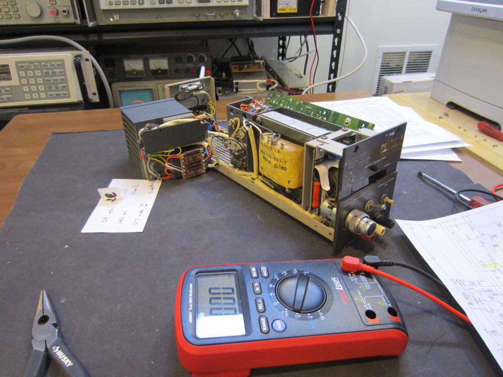
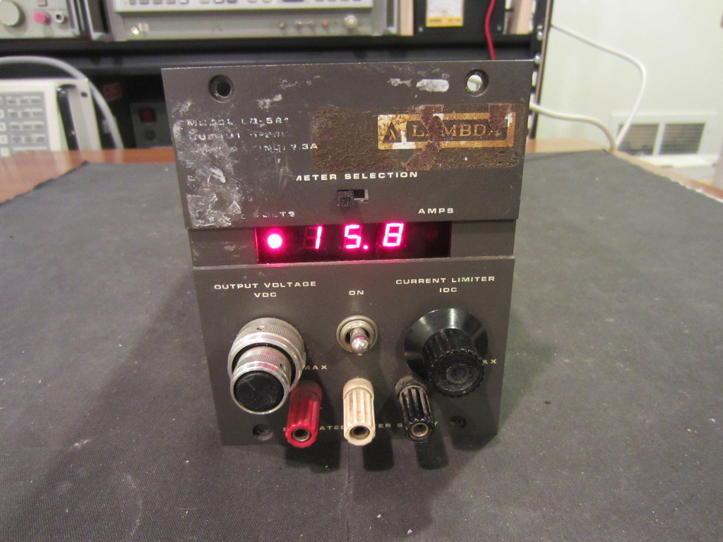
The unit I received did not display anything when powered on and the output voltage was stuck at 40 V regardless of the voltage adjustment potentiometer position. The latter behavior is a classic symptom of a blown pass transistor (i.e. shorted collector and emitter).
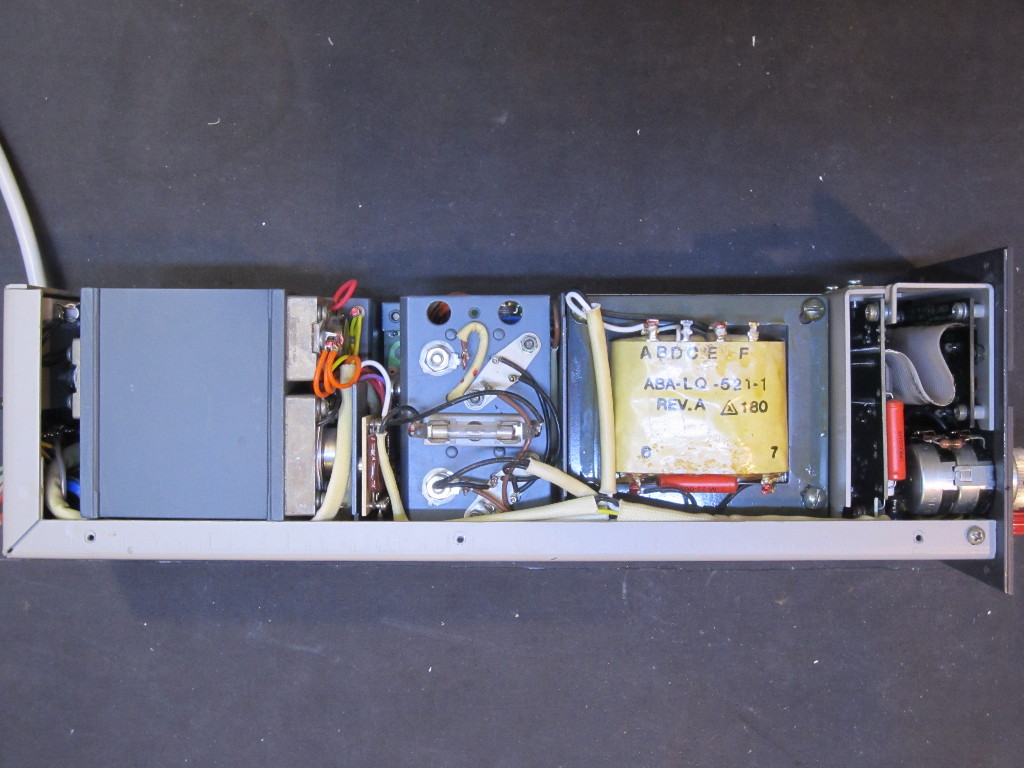
Upon opening up the case, you can see that everything is tightly fit inside. I was a little bit nervous at first as there was a piece of paper stuck on top of the transformer and has the word “fire” written on it. I wasn’t entirely sure what I was dealing with, perhaps somehow the circuit caught on fire before? Or could the power transformer be shorted somehow?
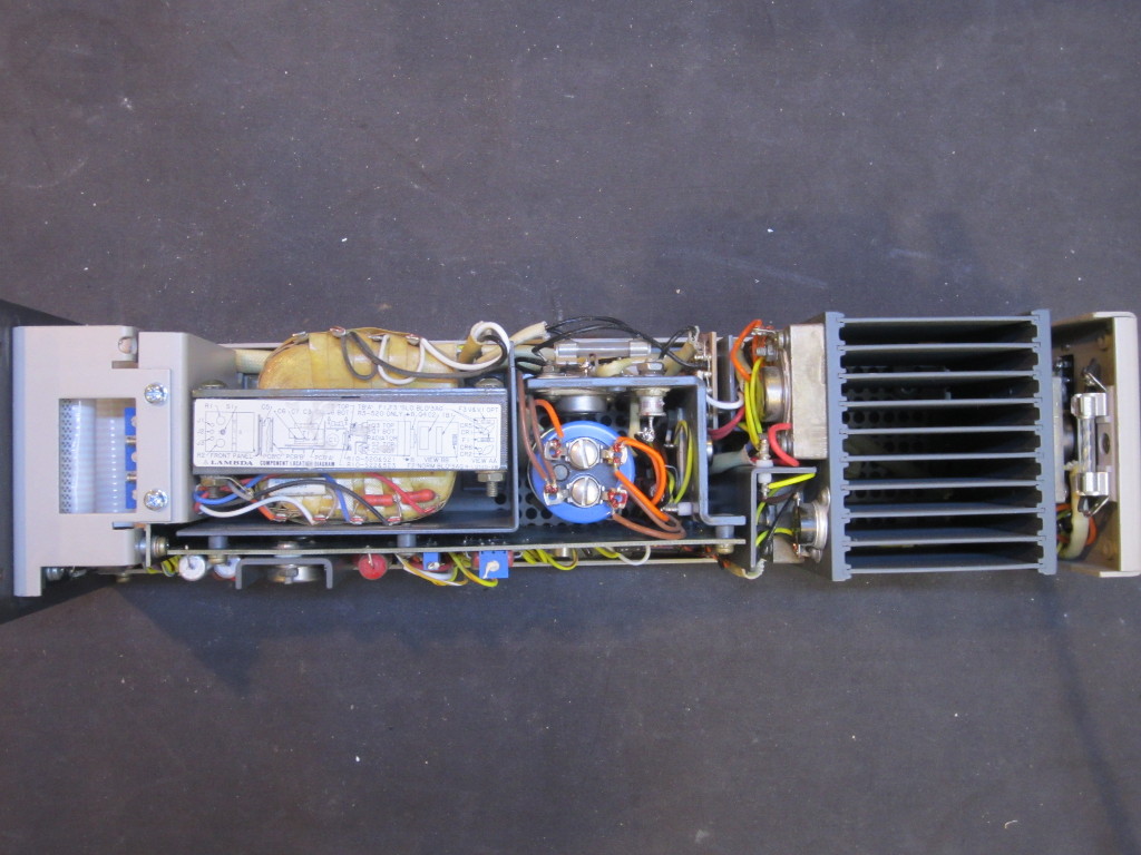
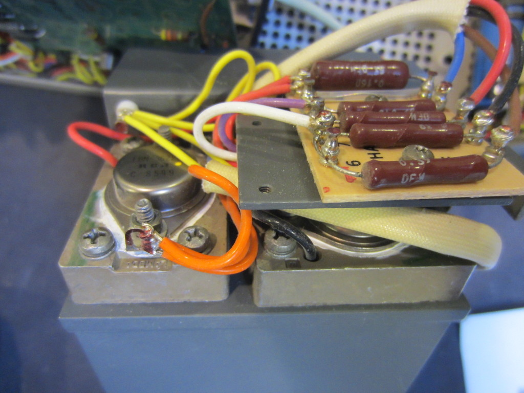
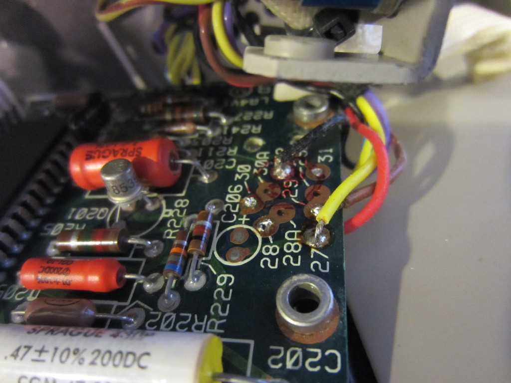
After some close inspection, I did find that one of the resistors (the one above the current adjustment potentiometer on the right below) was burnt and the underside of the flat cable above it was covered in soot. According to the service manual, the resistor (R11) should be a 1/2 W 182Ω one. If the power supply loses its regulation like its current state, the power dissipation on this resistor could go through the roof if the coarse/fine adjustment potentiometers are adjusted to their minimum values. And at 40V the power dissipation on this 182Ω resistor would be roughly 8.8W, which is almost 18 times its rated maximum power dissipation. So it makes sense to see this resistor burnt. Maybe this is what the sticker with “fire” written on it was referring to.
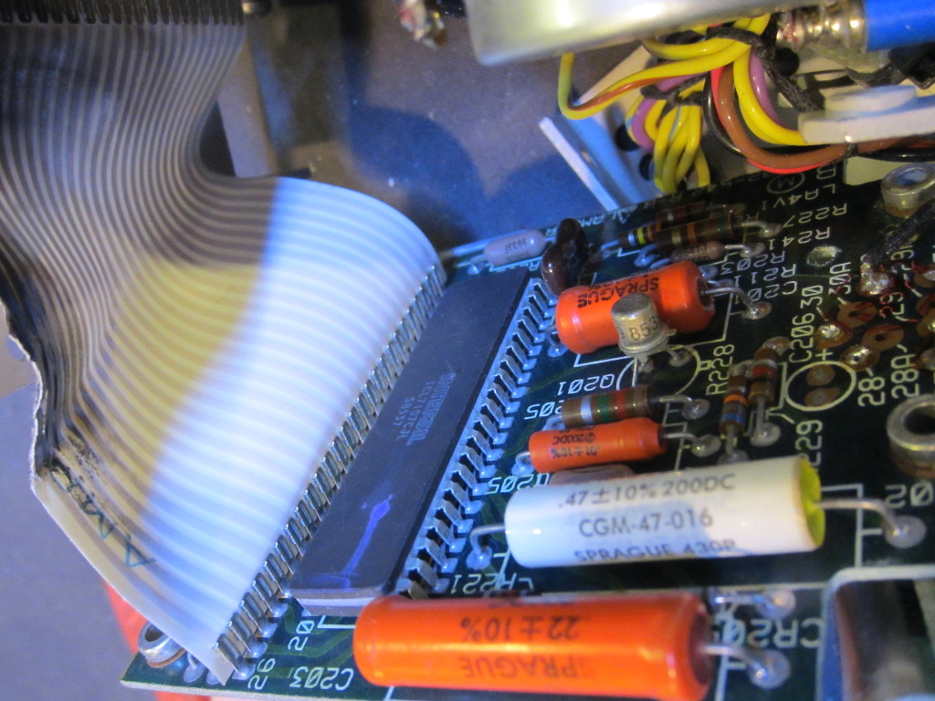
There is a single PCB on the other side of the power supply. The PCB is minimally populated. I suspect that the PCB is shared among the other power supplies in the LQ series and that explains why on this board there are many un-populated footprints. The two TO-3 devices on the PCB in the picture below are the 11.7V and 5V regulators.
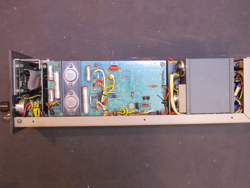
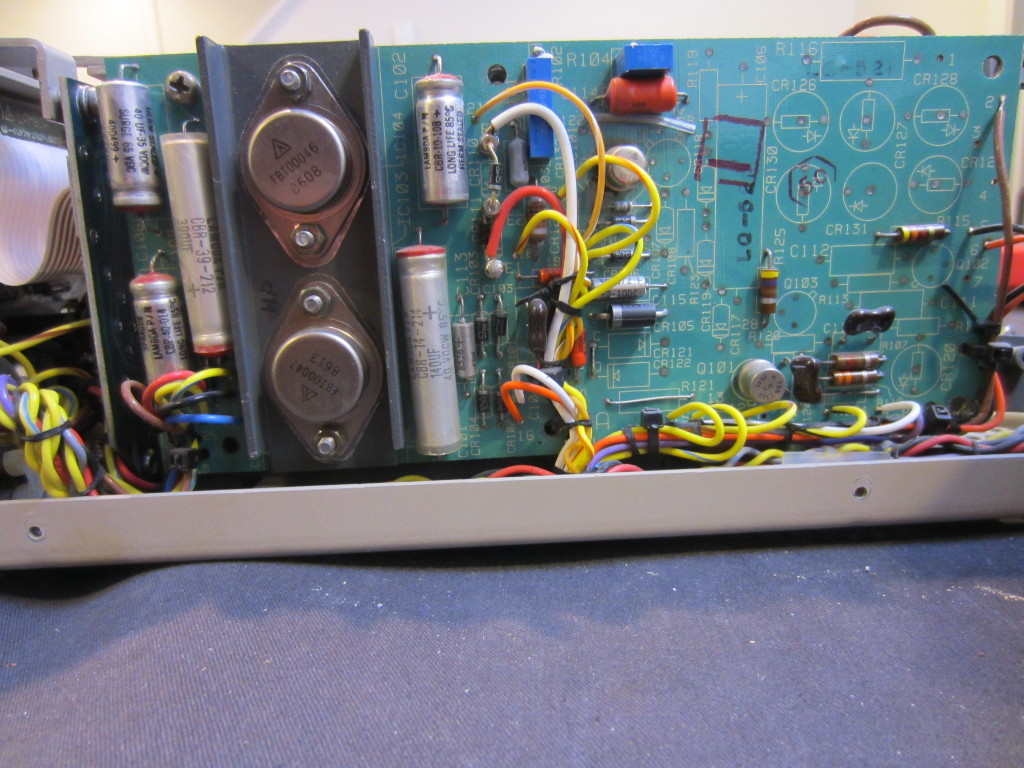
And here is a closeup of the main circuit board. The wiring inside the unit is quite messy. Although this kind of construction was quite common back in the 80’s, the tight spacing in this unit certainly makes it a lot more difficult to service.
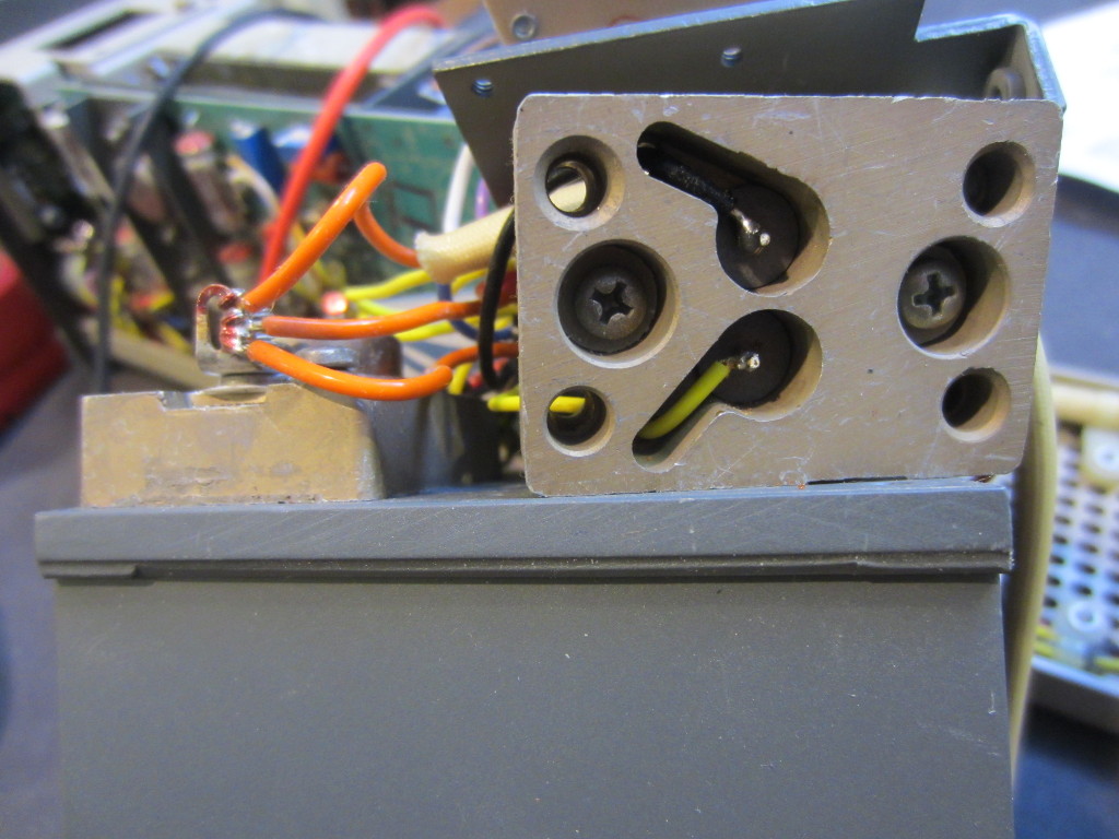
To examine the pass transistors, the heat sink block needs to be removed from the chassis first.
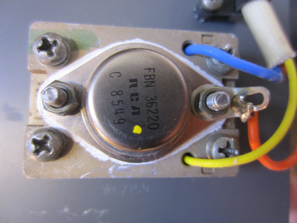
And because how these transistors are mounted, you cannot access the pins without first removing the smaller block from the heatsink. Here is a closeup picture of the power transistors.
The pass transistors used are RCA’s FBN-36220 NPN power transistors, which can be replaced with the ubiquitous 2N3055. If one of the transistors needs to be replaced, it is recommended that all the pass transistors be replaced at once as these transistors are hFE matched. A mismatch in hFE and other parameters could cause load to be distributed unevenly and cause stress and even failure of one of the pass elements.
I removed the power transistors from the heatsink one by one, and checked each individually after desoldering from the circuit. All transistors seemed to be fine. I did notice however that on one transistor the solder on the emitter pin was touching the housing (which is the collector) and thus causing a short. After I cleaned up the pin and re-soldered it, the collector emitter shorting problem went away.
Next I needed to find out why the 7 segment display was not showing any sign of life. After I removed the front panel display circuit board, it became clear. As it turned out, someone tried to service this power supply before. And for whatever reason, he desoldered the wires leading to the display board (perhaps trying to isolate the problem?). So I carefully soldered all the wires back in place.
Here is a picture of the display board. The display driver is an Intersil ICL7107 3 1/2 digit, LCD/LED display and A/D converter. This one used here is in a ceramic package.
Voila, the power supply is now back in life! I didn’t even need to do any calibration as everything looked to be right within spec.
The video below documented the repair process:

