Static fieldmeters (or electrostatic fieldmeters) are typically used for non-contact measurements of the electrostatic field strength (usually in kV) of charged objects. These are highly specialized test instruments and most hobbyists probably seldomly have the opportunity of coming across one. So in this post and a companion video towards the end, we will take a look at how it works and what’s inside.
An electrostatic fieldmeter comes in handy when handling ESD sensitive electronics components, especially those with metal oxide layers (e.g. MOSFET, CMOS chips). These devices are sensitive to ESD and a typical damaging voltage level is only several hundred volts. Most datasheet lists human-body model (HBM) and charged-device model (CDM) voltage figures. Although these specified voltage may seem to be high (usually hundreds to several thousand volts), they can be exceeded in dry environments when electrical insulating materials are present.
Typically a static fieldmeter works by using a ground referenced capacitive sensor. When the sensor is exposed to an external electrostatic field, charge is induced on the sensor plate and the voltage generated across the sensor is proportional to the field strength. When the sensor is calibrated (at a given distance, typically one inch for example), we can calculate the actual field strength via the measured induced voltage. This US Patent (4716371 A) describes the operating principle in a little more detail.
More advanced electrostatic fieldmeters sometimes utilize the so-called Kelvin vibrating capacitive sensor method. By vibrating the sensing plate (usually a sinusoidal function), the distance dependency can be removed or greatly reduced.
The meter we are going to examine is a roughly 20 year old Plastic Systems (now ESD Systems) 42721 static fieldmeter (picture shown below). Because the case needs to be ground referenced, the plastic material used to make the case is actually conductive (in GΩ range). During normal use, when a grounded operator holds the meter the meter becomes grounded as well. Alternatively, a grounding wire can be connected directly to the device.
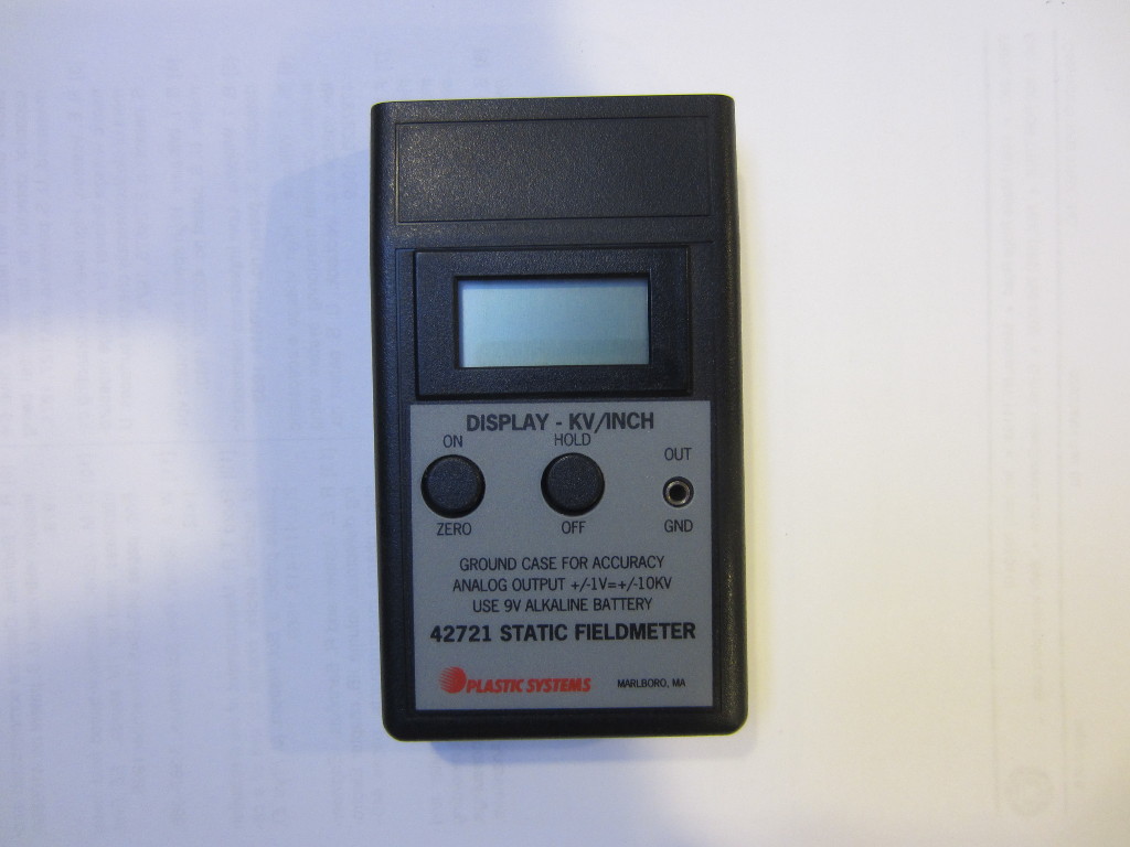
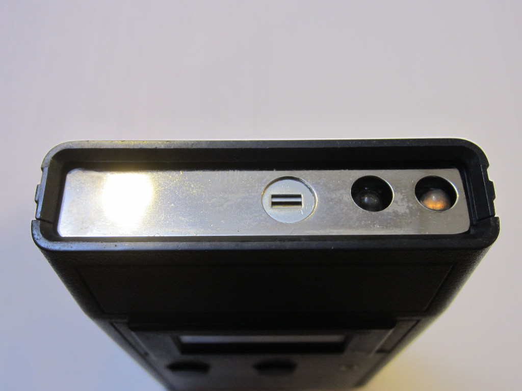
From the picture below, you can see the sensor located towards the middle on the top side of the instrument. The two LEDs are arranged at an angle and are alternately lit in operation. This arrangement helps users to visually identify the correct operating distance at which the two light spots become one.
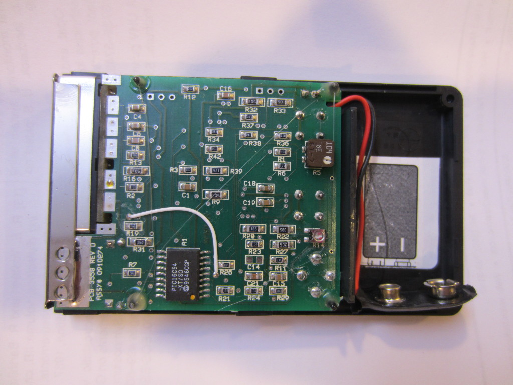
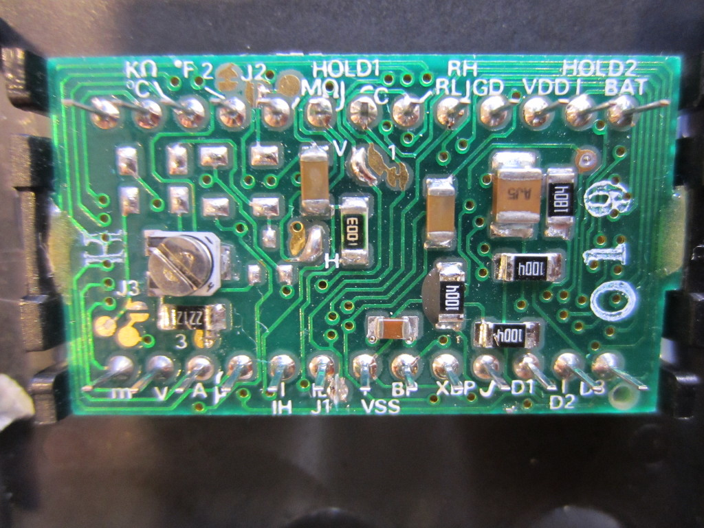
After removing the back cover, we can see the back side of the circuit board. The main chip used in this fieldmeter is a Microchip PIC16C54 8-bit microcontroller. The datecode suggests that this unit was made sometime after 1995.
|
|
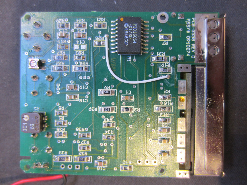
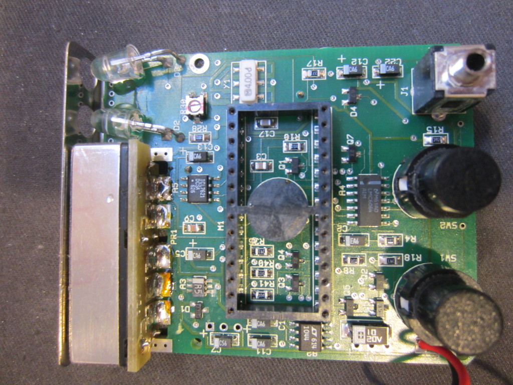
On the flip side of the board, we can see the analog circuitry. The main amplifier for the capacitive sensor is a ICL7621 high input impedance, ultra low input current and low drift operational amplifier. These properties are critical for amplifying the small DC signal generated on the capacitive element. To the right of the picture, there is an LMC6064 precision quad micropower operational amplifier. A switched capacitor voltage converter LTC1044 is used to generate the negative voltage needed by ICL7621 (and possibly the LCD).
Here is a picture of the LCD module, it plugs into the socket on the main board.
Finally, here is a video detailing the analysis and the teardown:

