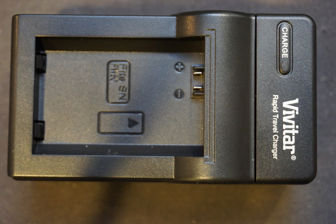
I just picked up a charger along with a couple of NP-FW50 spare batteries for my new Sony Alpha A6000 mirrorless digital camera. The Sony branded charger is ridiculously expensive, so I opted for an aftermarket Vivitar branded one (VIV-QCB-104), which retails for under $10. The charger is rated at 8.4V with maximum charging current of 600mA. Spec-wise, it looks fine for the NP-FW50 1Ah 7.4V battery pack.
The first thing I noticed about this charger though is its extreme light weight. Also the thermistor contact was omitted from the charger output. The omission of the temperature sensing terminal concerned me as should there be a malfunction of the charger or the battery, the battery could overheat and catch on fire. Thermal cutoff would be the last defense. Without such mechanism, unattended charging would be dangerous.
So out of curiosity, I decided to look a little further. The teardown video is included towards the end.
One neat design of this charger is that the battery adapter plate is removable. This means that you could potentially use this charger to charge different battery packs as long as you have the correct mating plate. At least in theory anyway. I don’t know if you can buy the battery adapter plate separately however.
If you look at the battery plate to charger mating contacts below, you will see that the middle contact point for the thermistor is present. But the middle pin is shorted to the negative terminal on the battery plate side so clearly this pin is not used for temperature sensing in this charger.
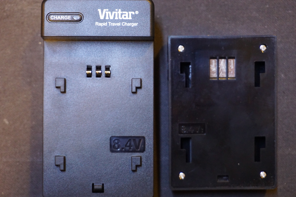
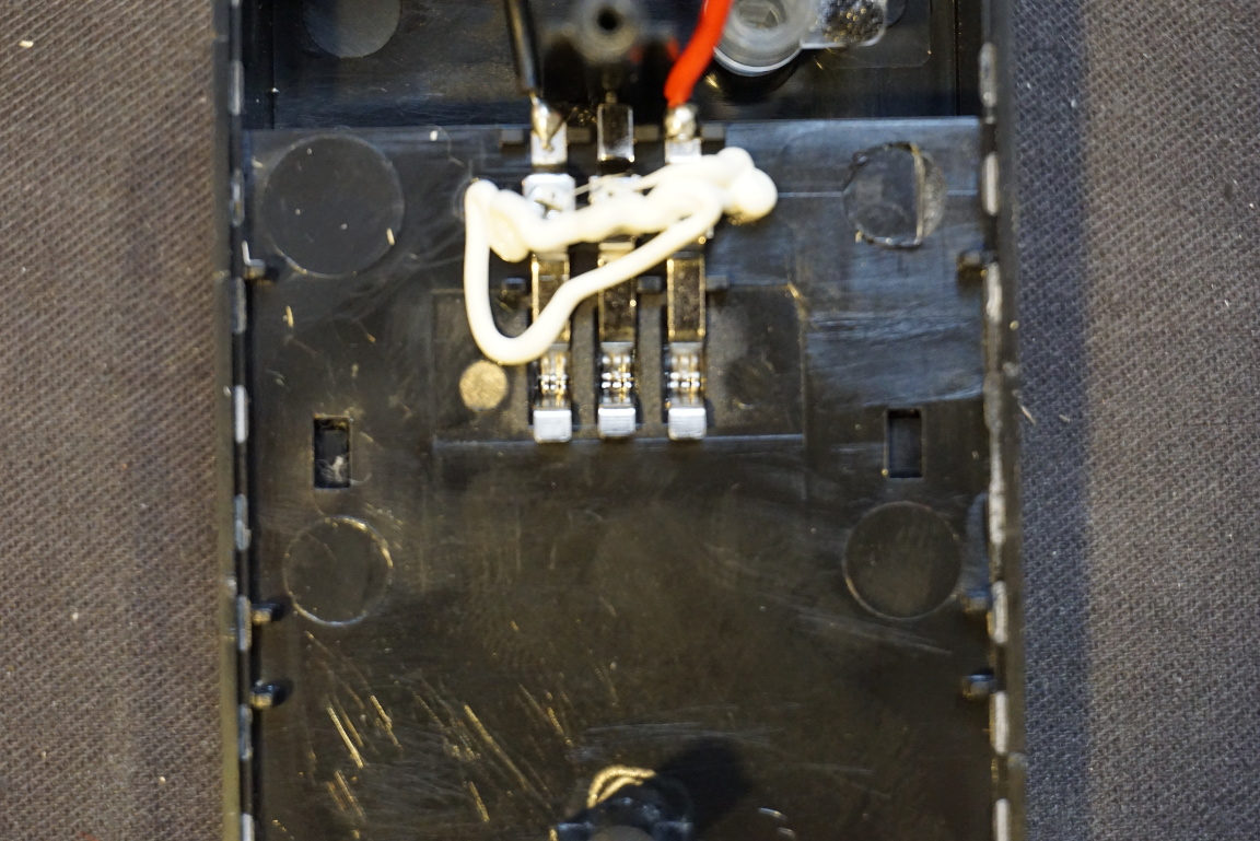
Looking at the charger side confirms this. As you can see from the picture below, nothing is connected to the center pin on the charger side.
The circuit board itself though looks surprisingly clean and well designed. It does not use any dedicated lithium ion battery charging ICs however. Rather a MC34063A buck/boost DC-DC converter chip is used to provide the current limited 8.4V constant voltage. This arrangement is less ideal then the typical lithium ion battery charging technique. Typically, the charging current is held constant until the voltage reaches a certain threshold and then the charger switches to constant voltage mode. Once the charging current drops under a predetermined threshold the charging is done. The charging current under constant voltage charging however, monotonically decreases from the get go so it usually takes much longer to obtain a full charge. But the good news here is that overcharging is unlikely as the charging voltage is fixed to the correct battery terminal voltage.
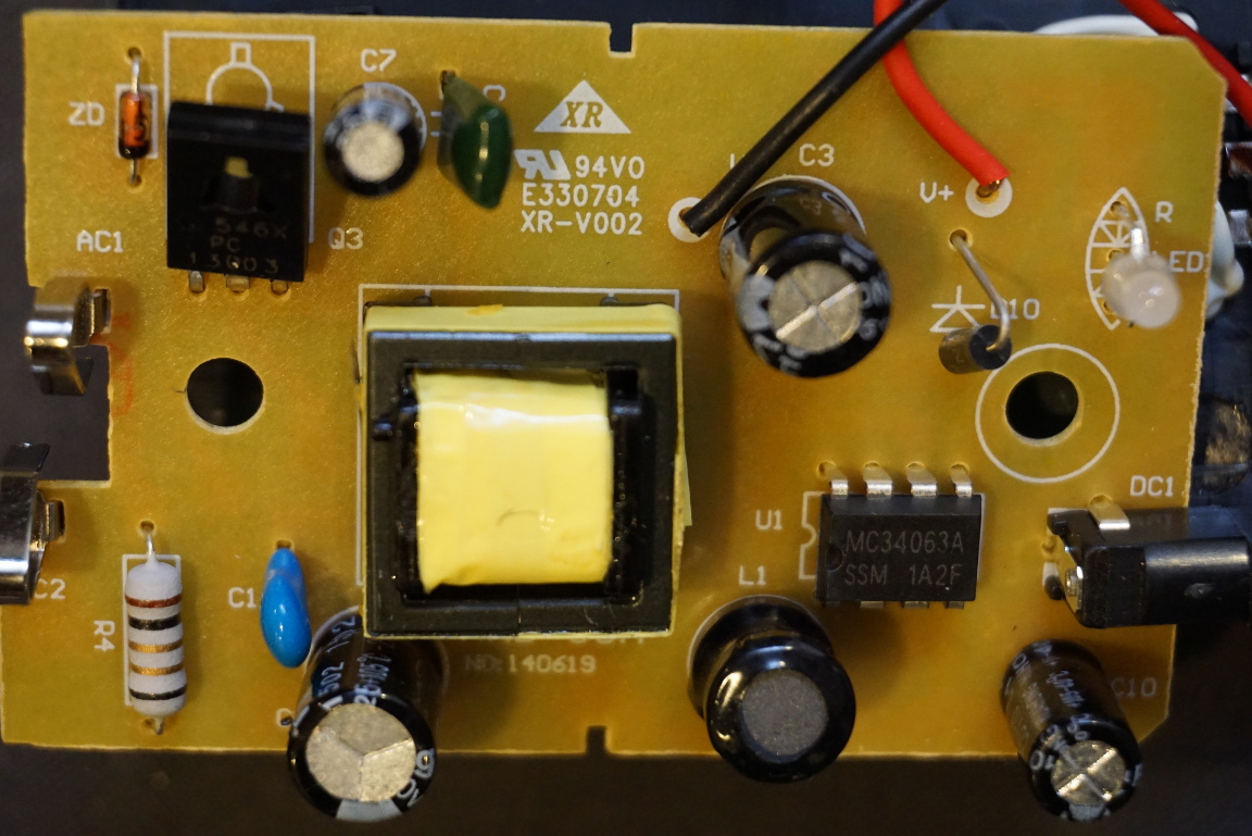
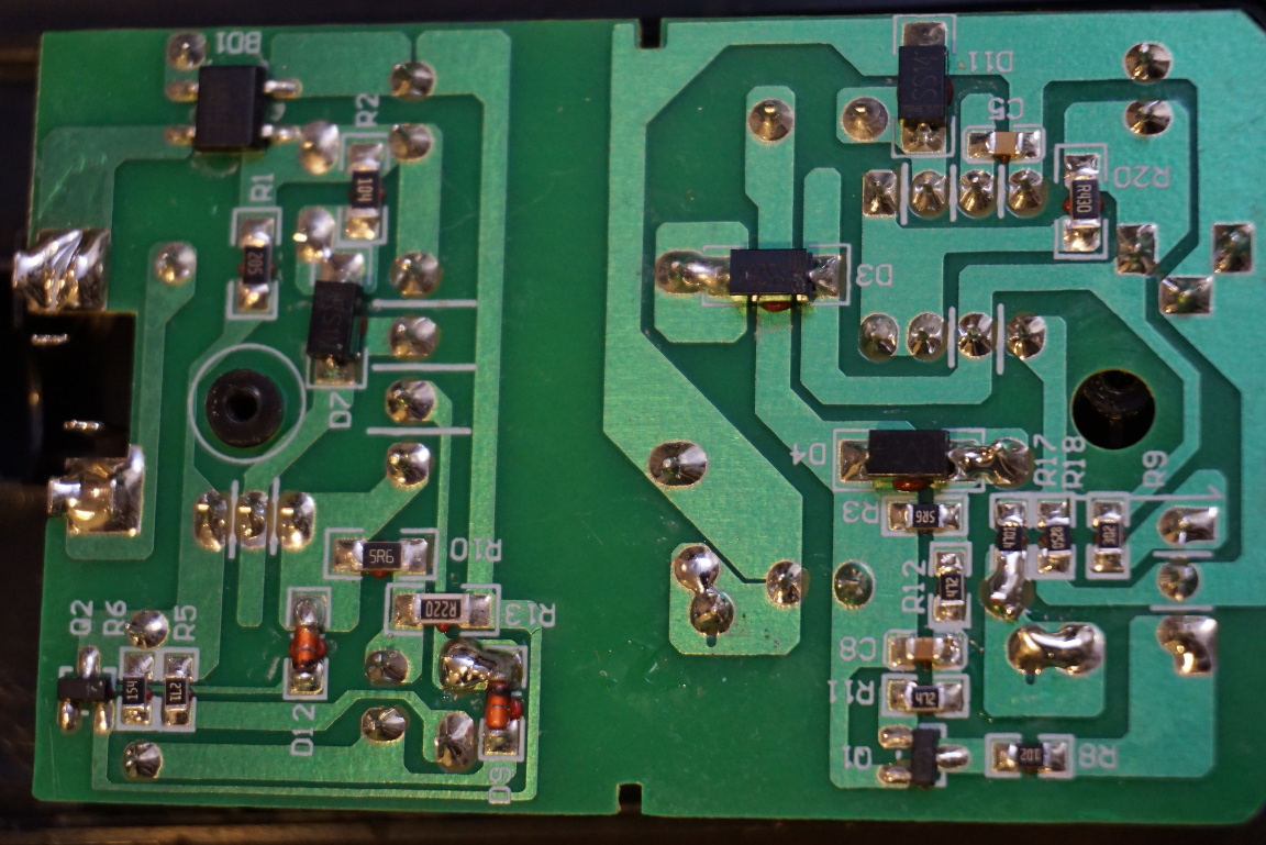
From the circuit board bottom view below, you can clearly see the large isolation gap between the primary of the switching transformer and the secondary. Essentially, this charger consist of two independent DC-DC converters. The first one is a single transistor step down converter which converts the mains voltage down to a voltage suitable for the MC34063A. This voltage is unregulated as there is no feedback between the secondary and the primary. Then the MC34063A is configured as a buck converter to convert the unregulated transformer output (rectified) to a fixed 8.4V voltage.
Since there is no power factor correction (PFC) circuitry on the primary side, the power factor is low (measured at just 0.5).
So, you should be fine using this charger to charge your NP-FW50 batteries. Although it would be a lot safer if it had the proper thermal cutoff circuitry.

