In my previous blog posts, I did a teardown of the Symmetricom/Datum 8040 Rubidium frequency standard and modified the 1PPS output by expanding the pulse width from just around 10µs to roughly 50% duty cycle. There were some questions regarding the clock jitter introduced by the 555 monostable circuit. So let’s take a more detailed look in this post.
To accurately measure clock jitter is a bit difficult with the equipment I have. Since there is no trigger jitter specifications for my Rigol DS1052E, we have to make several assumptions. For simplicity, I assumed that trigger jitter from the Rigol scope is negligible and the jitter from the 1PPS 10µs output can also be ignored.
The following scope capture shows the original 1PPS pulse superimposed with the width-expanded pulse. All the captured data is triggered on the 10µs pulse.
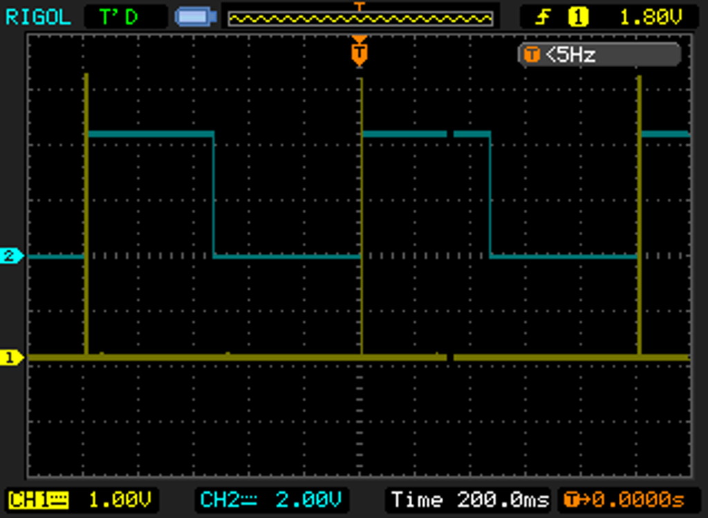
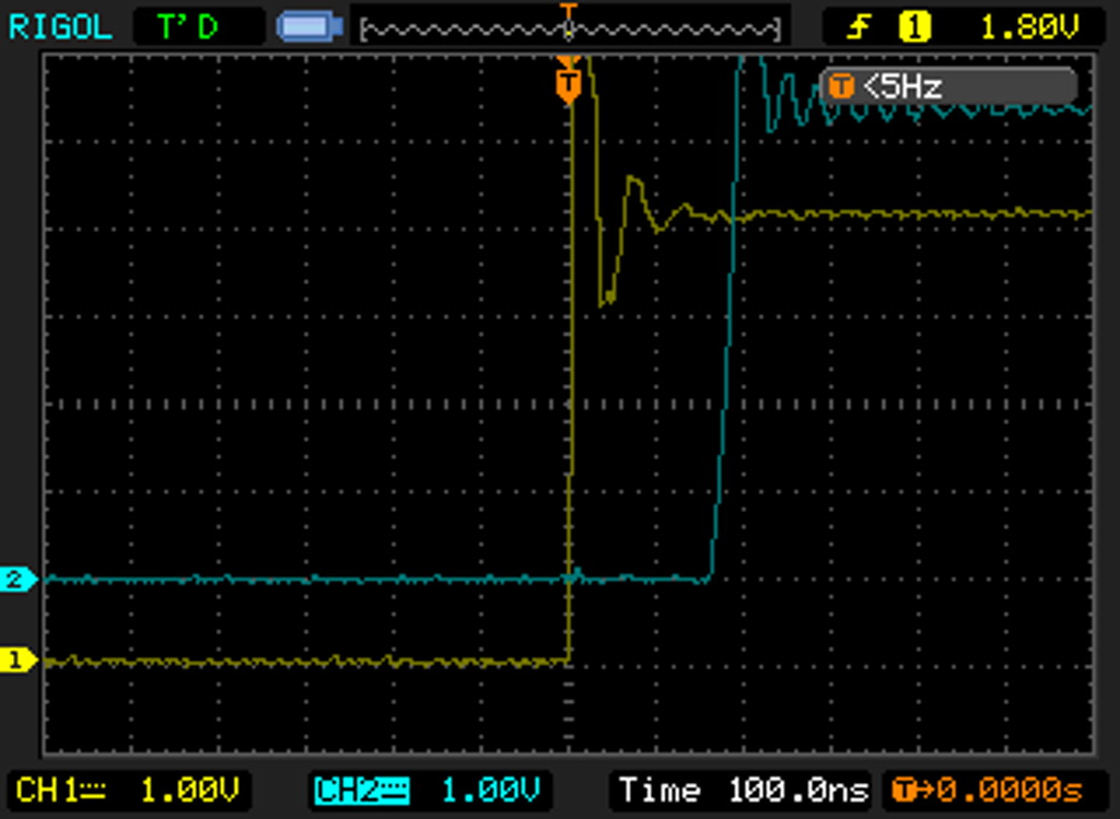
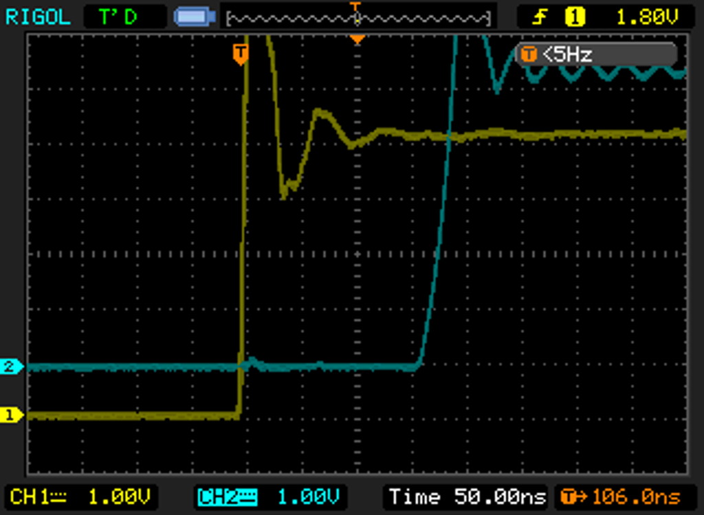
Here we can see the delay introduced by the pulse expander circuit. The cables from both 1PPS outputs are of the same length so the propagation delays can be ignored. Here you can see that the delay is just above 150 ns. The excessive ringing is due to the fact the channels are not 50Ω terminated. Also you can see that the rise time of our expanded signal is not as good as the rise time of the original 10µs pulse.
The kind of jitter we can measure using this setup is the long term jitter. For that I turned on the infinite persistence for both channels and let the scope gather data for about ten minutes. And as expected, the traces thickened somewhat due to clock jitters. Although we assumed that the jitter was only coming from the pulse expander, in reality the jitter we see here is a combination of the scope trigger jitter, the jitter of the 1PPS 10µs pulse from the Rubidium standard and the jitter from our pulse expander.
By extending the timebase, we can see the jitter more clearly. The jitter you see here, roughly 1ns, is the maximum clock jitter over a period of ten minutes. Since there is no intensity grading, the jitter spans almost a DIV uniformly. But in practice the jitter is more of a Gaussian distribution around the trigger point so the RMS of the jitter should be just around 700 ps. I wouldn’t be surprised that a significant portion of this jitter is inherent to the triggering circuitry of DS1052E.
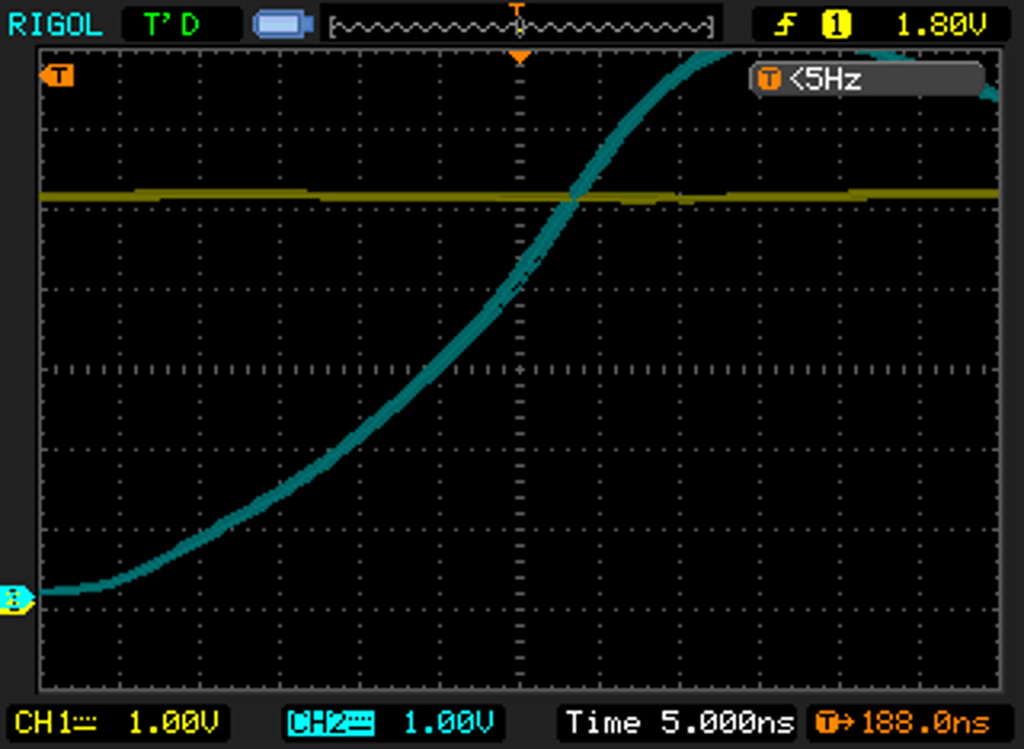
And the clock-to-clock jitter should be far smaller than the averaged long term jitter we see here.

