I picked up an HP 7044A X-Y recorder on eBay recently. This one was made in the early 1980’s and by today’s technology standard it is rather ancient. And because of this, it is very easy to interface with as the input is completely analog. My plan was to do some experiments down the road using the X-Y movements capability of this HP recorder.
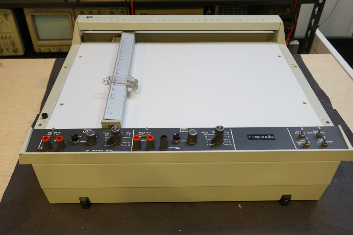
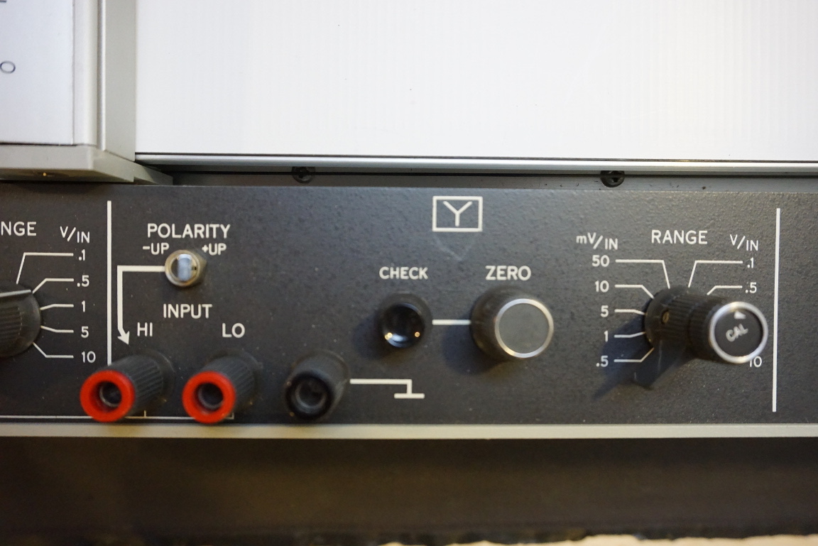
The control panel of this X-Y recorder is very simple. It is not surprising that the input controls look like those of an oscilloscope. In a sense, an X-Y recorder functions very similar to an oscilloscope in its X-Y mode. The input sensitivity for the 7044A ranges from 0.5mV/inch all the way to 10V/inch in 10 steps and a calibration potentiometer on each channel can be used to fine-tune the sensitivity within each range.
Because the input impedance for each channel is very high (at 1 MΩ), the “check” momentary push button is used to short out the inputs when setting the zero location of the head. Without shorting the inputs, the electromagnetic interference from the environment would cause the servo motors to vibrate violently when the input sensitivity is less than 50mV/inch.
|
|
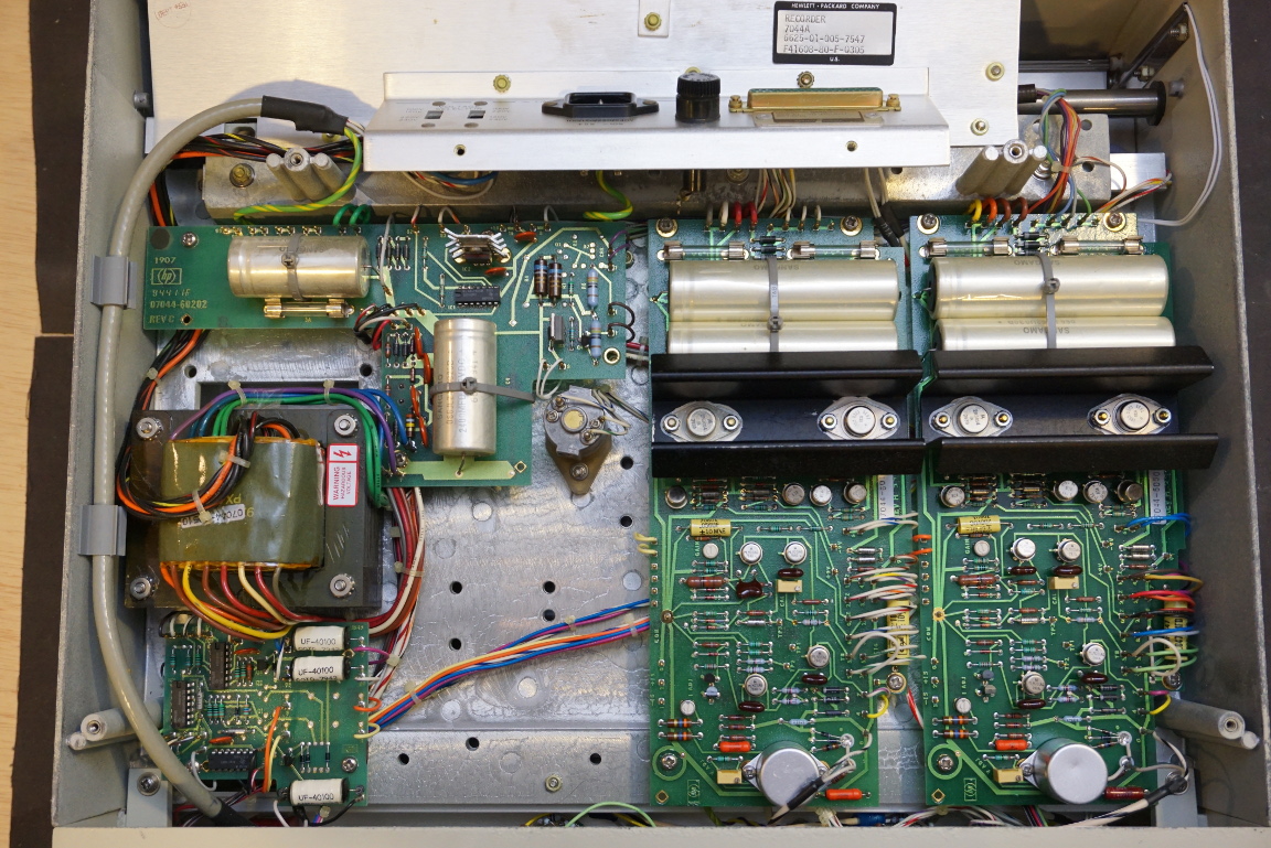
The electronics can be accessed by removing the bottom panel. The circuit roughly divides into two portions. The left half is primarily the power supply circuit and the right half houses the two identical channels, one for driving the X axis and one for driving the Y axis.
|
|
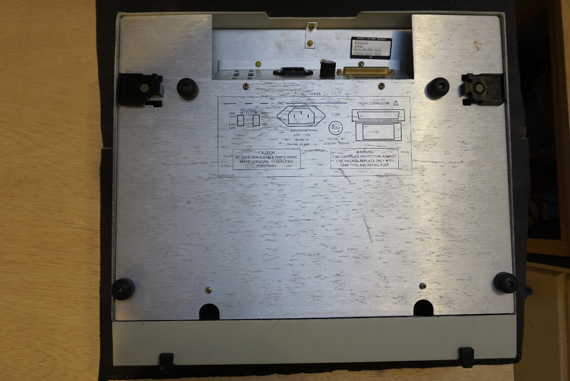
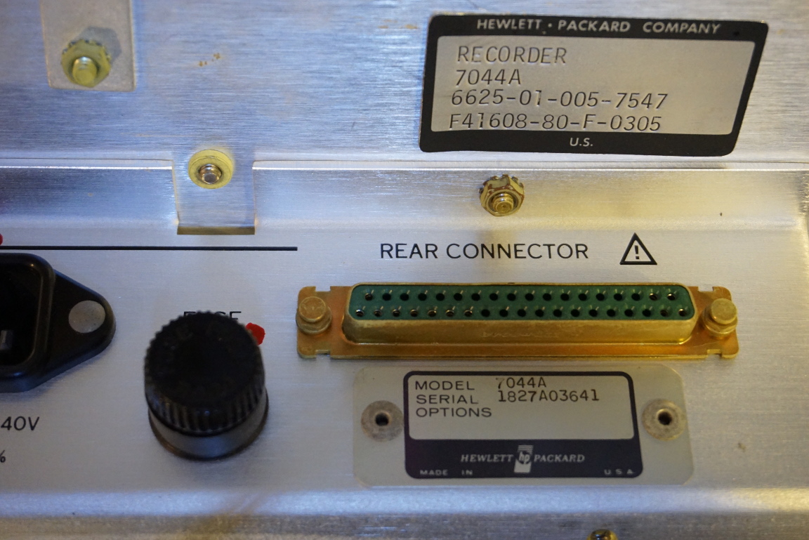
There is a D-SUB connector at the rear panel, which can be used to supply X/Y inputs and control the recording.
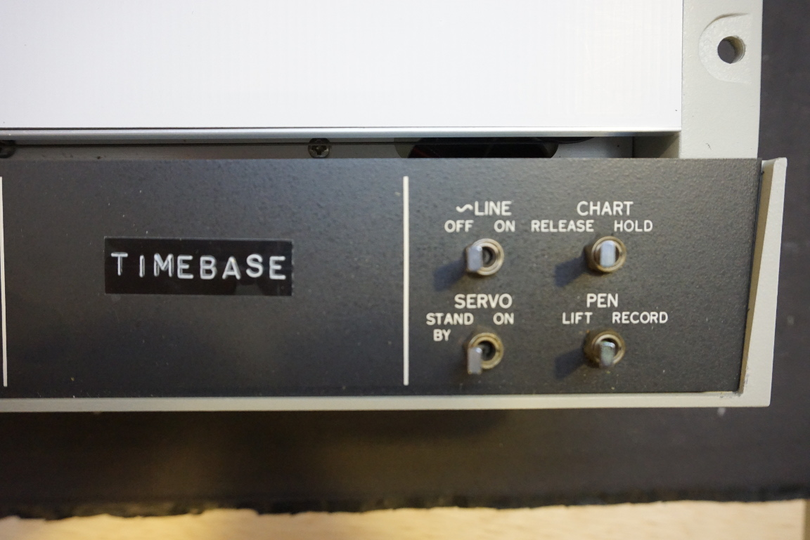
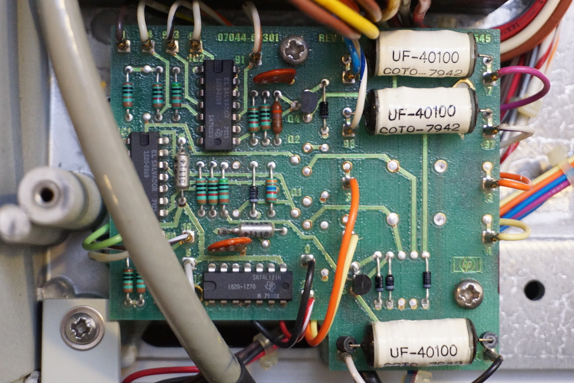
Here is a close-up picture of the power transformer and some digital circuitry. I am not entirely sure what this circuit board does however. The 74L121 is a multivibrator chip so it is doing some sort of timing job. Although there is a “timebase” sticker on the recorder panel, it doesn’t seem to have any controls on the panel. Maybe it is used to generate the timing signal for the servo motors.
I couldn’t find any service manual or schematics for the HP 7044A. But since HP 7015B is roughly from the same era, the core circuitry should be pretty close.
|
|
 |
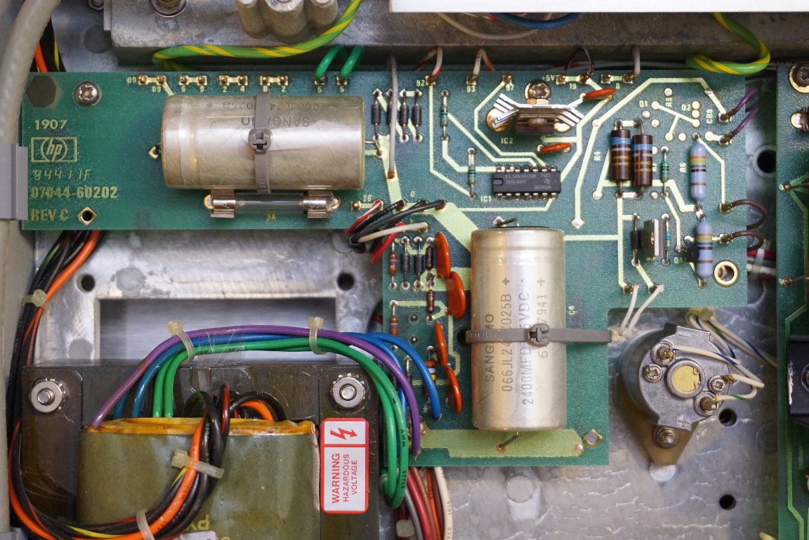
The picture to the left below is the power supply board for positive and negative regulated DC voltages used in the rest of the system. If you look closer, you will see two voltage doublers towards the middle of the board. These voltage doublers are for the autogrip function. They supply roughly ±400V or so high voltage to the metal plates beneath the plotter surface so when energized the electrostatic force holds the paper in place. The two red high voltage wires can be seen from the picture to the right below.
|
|
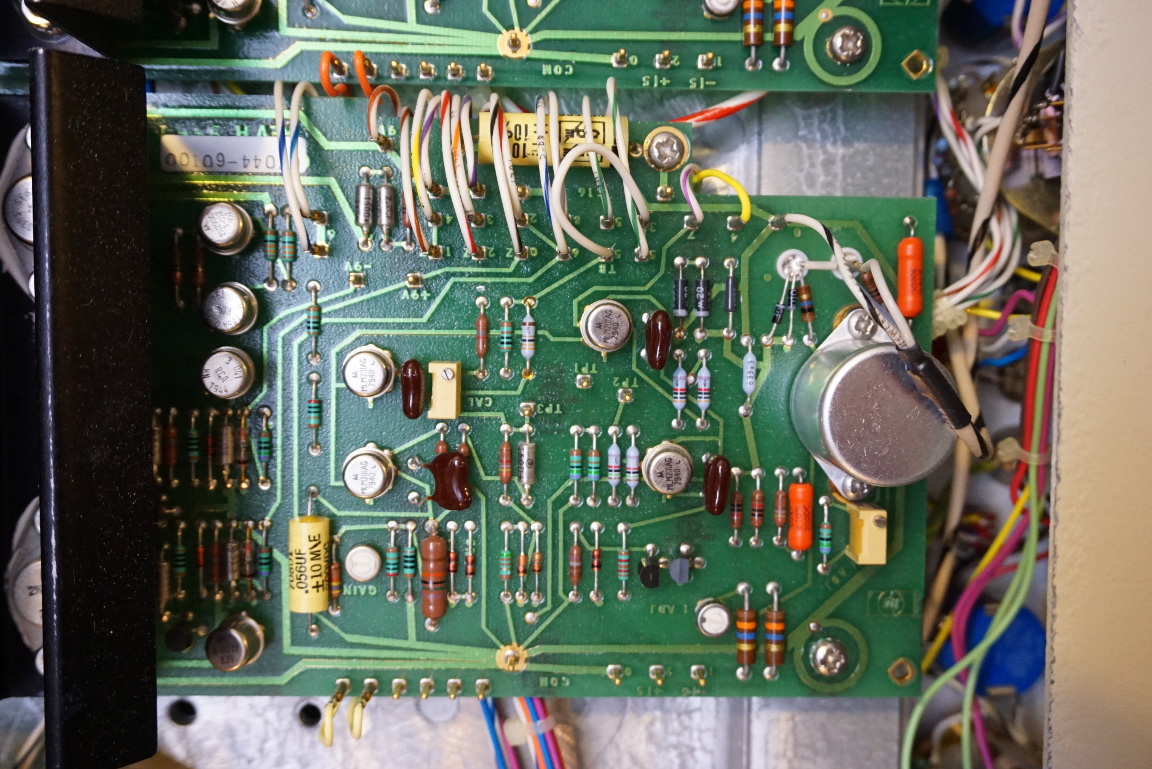
The picture to the left below shows the X channel driver board, the Y channel board is identical. And the picture to the right shows one of the complementary output stages (2N3054 and 2N5956) that drives the servo motor.
|
|
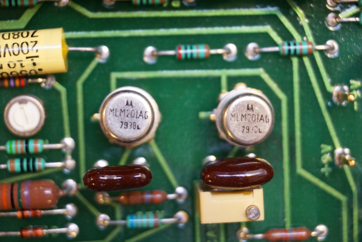
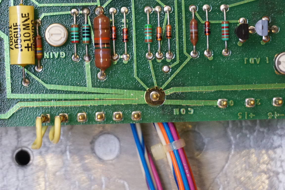
Here is a close-up showing the OpAmps used on the driver board (MLM201AG). And the picture to the right shows the grounding point of the channel.
|
|
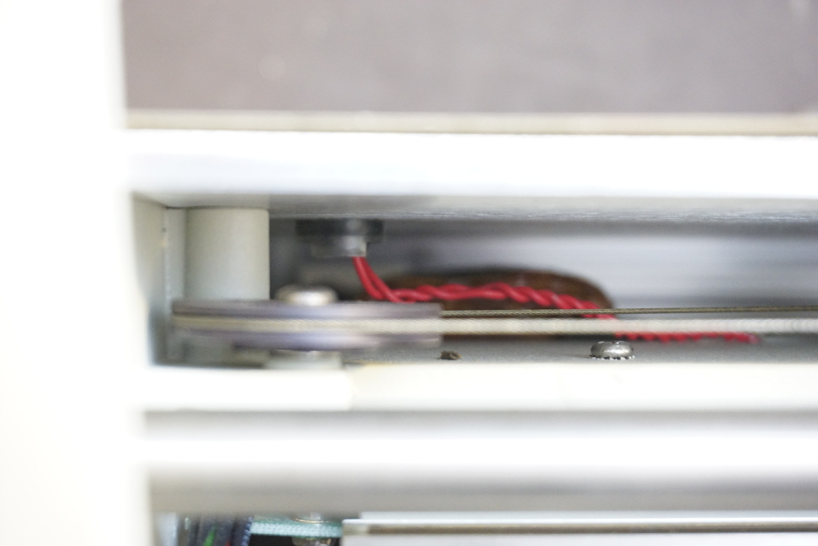
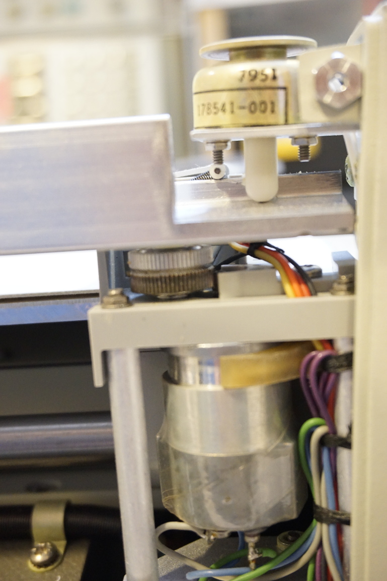
Here is a picture showing the pen-down solenoid. The X axis motor can also be seen.
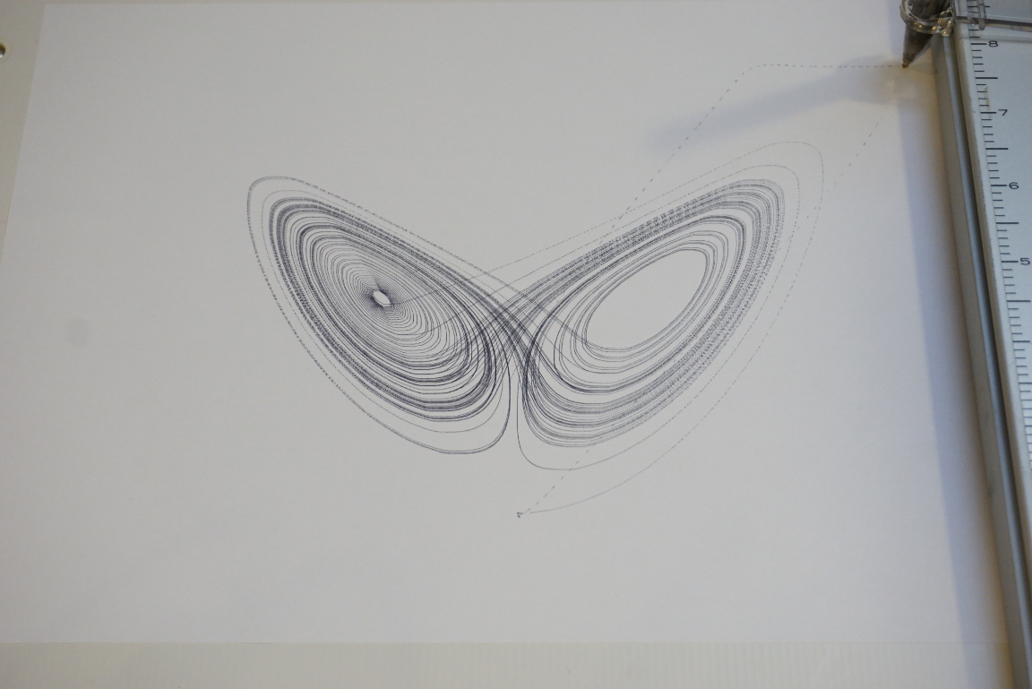
To test the recorder, I wrote a simple program using Arduino Due that generates a Lorenz attractor. The min/max boundaries for each axis were obtained prior and they are used to map the curve to the first quadrant since 7044A can only plot signals within a single quadrant at a time. Arduino Due is convenient because it has two 12bit DAC outputs which can be used to drive the X and Y channel.
Unlike using an oscilloscope, the recorder cannot record data that changes faster than a few Hertz. To slow down the output, you can either decrease the time interval (I chose 0.001) or add in additional delays. I used serial output to slow things down a bit, this is convenient as I could use the data when debugging the program as well.
Here is the code listing for generating the Lorenz Attractor using Arduino Due:
double x = 0.1;
double y = 0.0;
double z = 0.0;

double a = 10.0;
double b = 28.0;
double c = 8.0/3.0;
double t = 0.001;

double minX = -20.0745;
double maxX = 21.5292;
double minY = -26.8399;
double maxY = 29.4550;
double minZ = 0.0;
double maxZ = 54.3201;

double xt, yt, zt;
double mappedX, mappedY, mappedZ;

int Map(double x, double inMin, double inMax, double outMin, double outMax) {
  double temp = (x - inMin) * (outMax - outMin) / (inMax - inMin) + outMin;
  return  (int) (temp + 0.5);
}

void setup() {
  Serial.begin(115200);

  analogWriteResolution(12);
}

void loop() {
  xt = x + t * a * (y - x);
  yt = y + t * (x * (b - z) - y);
  zt = z + t * (x * y - c * z);

  x = xt;
  y = yt;
  z = zt;

  mappedX = Map(x, minX, maxX, 0, 4095);
  mappedY = Map(y, minY, maxY, 0, 4095);
  mappedZ = Map(z, minZ, maxZ, 0, 4095);

  Serial.print(mappedX);Serial.print(" ");
  Serial.print(mappedY);Serial.print(" ");
  Serial.print(mappedZ);Serial.println();

  analogWrite(DAC0, mappedX);
  analogWrite(DAC1, mappedZ);
}
And finally, you can watch a video of the teardown and experiment below:

