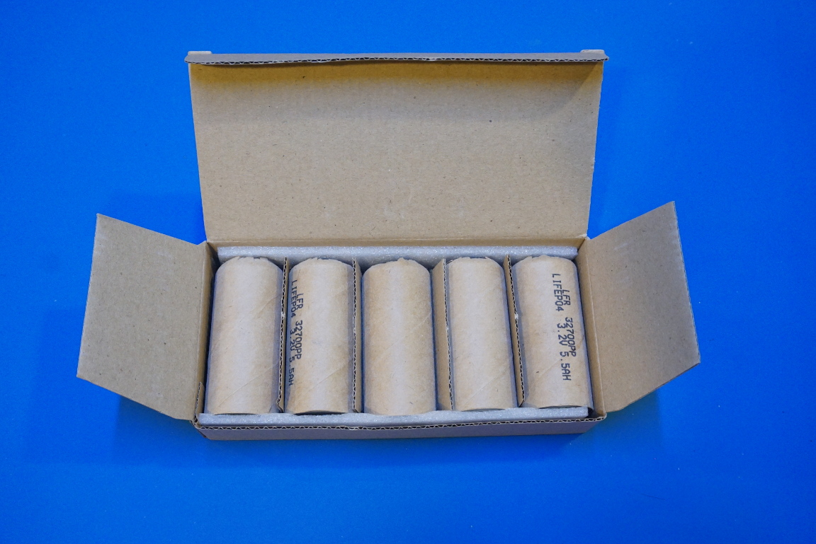
During the past couple of weeks I have been busy making a large battery bank using the eighty 32650 LiFePO4 cells I bought on eBay. The battery bank I am building is a 12V (13.2V nominal) 4S/20P one. With each cell rated at 5.5Ah the battery bank has a capacity of 110Ah, which is just under 1.5kWh.
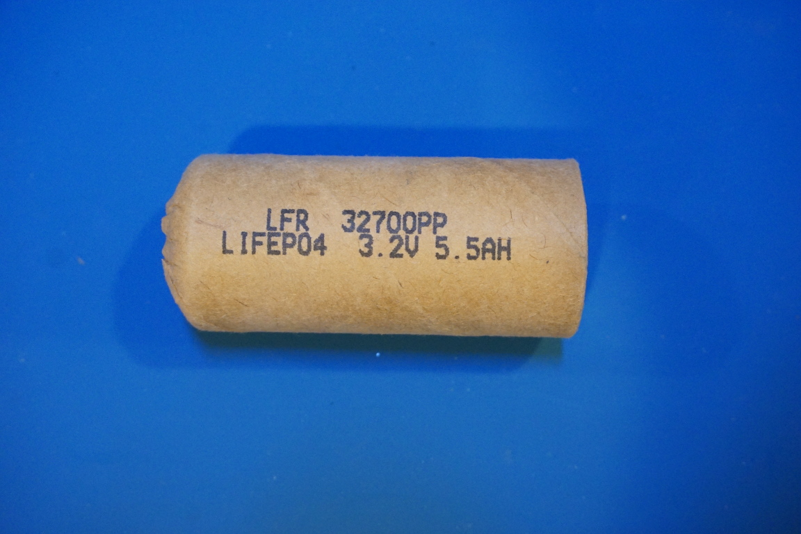
While These cells are marked as 32700 they are technically still 32650 cells according to the datasheet, which is a little bit confusing. Since I am making a custom battery bank the actual cell dimension is not as critical.
|
|
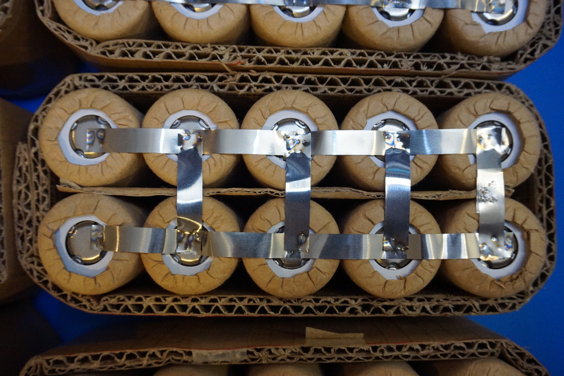
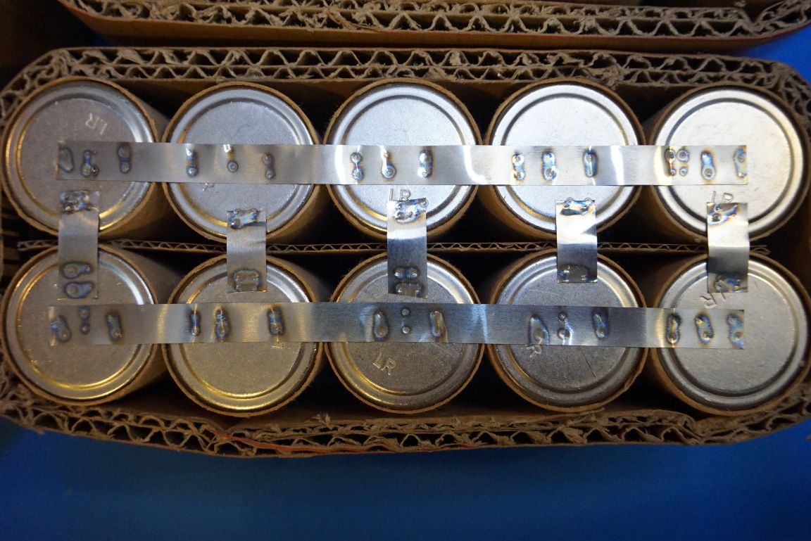
For each paralleled group, there are twenty cells. I arranged them in 2 by 5 groups and paralleled each two groups of cells further together. In my opinion, this is a little easier to work with given the smaller size of each group. The cells within each group are welded together using 8mm nickel strips. If you are interested in making a spot welder yourself, you can check out my earlier post on how to make one.
Ideally, each cell should be separated using plastic cell spacers. Besides providing structural support, spacers also allow airflow among cells. This is helpful for heat dissipation and is crucial if Li-ion batteries are used, as thermal runaway can become a fire hazard. Li-ion batteries heat up when they are grossly over charged or discharged at higher than maximum specified current.
I used cardboard instead to group the batteries together since the batteries I used are LiFePO4 cells. This cell chemistry does not have the thermal runaway problem as Li-ion. As you will see later, the battery management system (BMS) I am using also limits the overall discharging current to around 100A. Since I have twenty cells in parallel, this overall current translates to just 5A per cell. At 1C discharge rate, the heat generated is negligible.
I did not take into account the possibility of individual cell failures within each paralleled group however. This could be a problem as some of my viewers had suggested. In this case, a bad cell could potentially damage its belonging group if not the entire battery bank. But for stationary use with a power inverter, this failure mode is highly unlikely.
|
|
Here is a video I made a couple of weeks (see below) ago on using the spot welder to make these 2×5 cell groups.
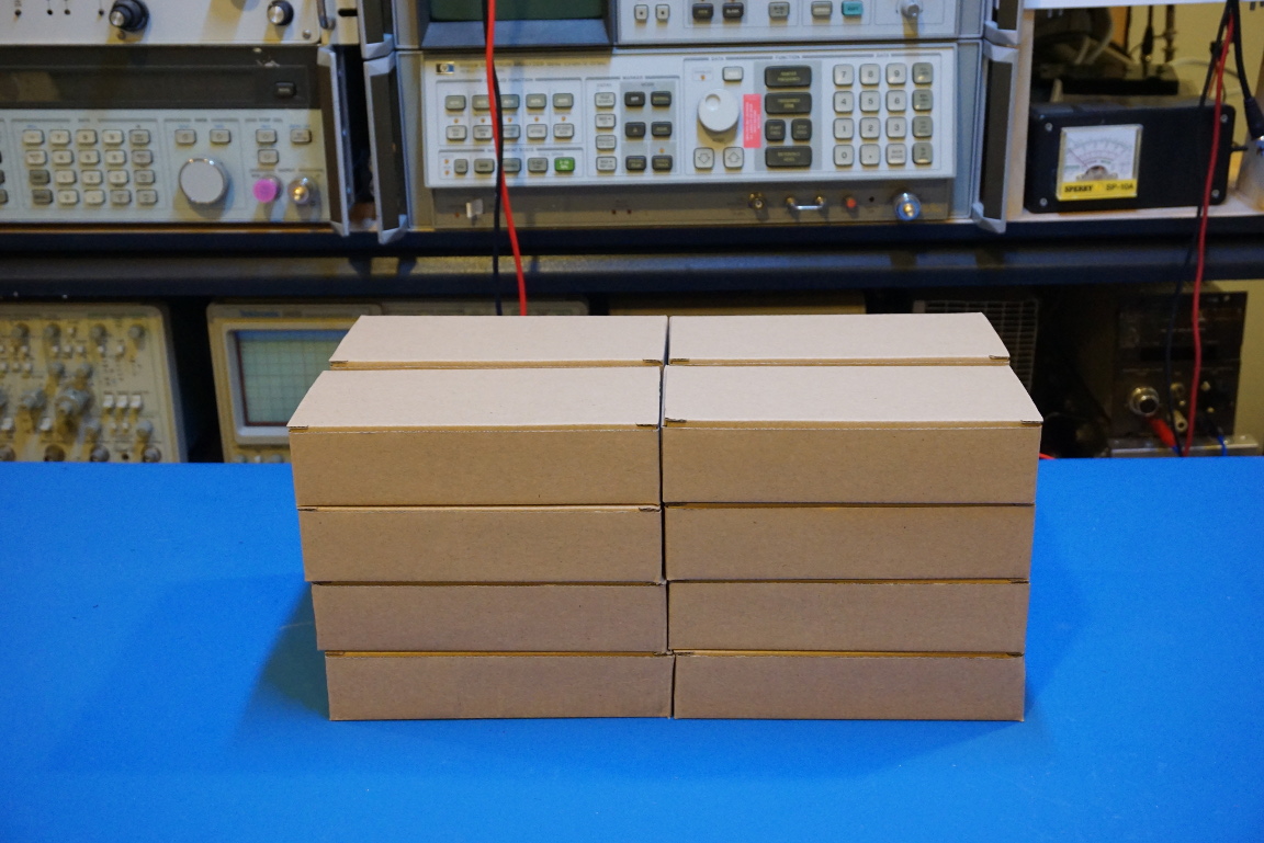
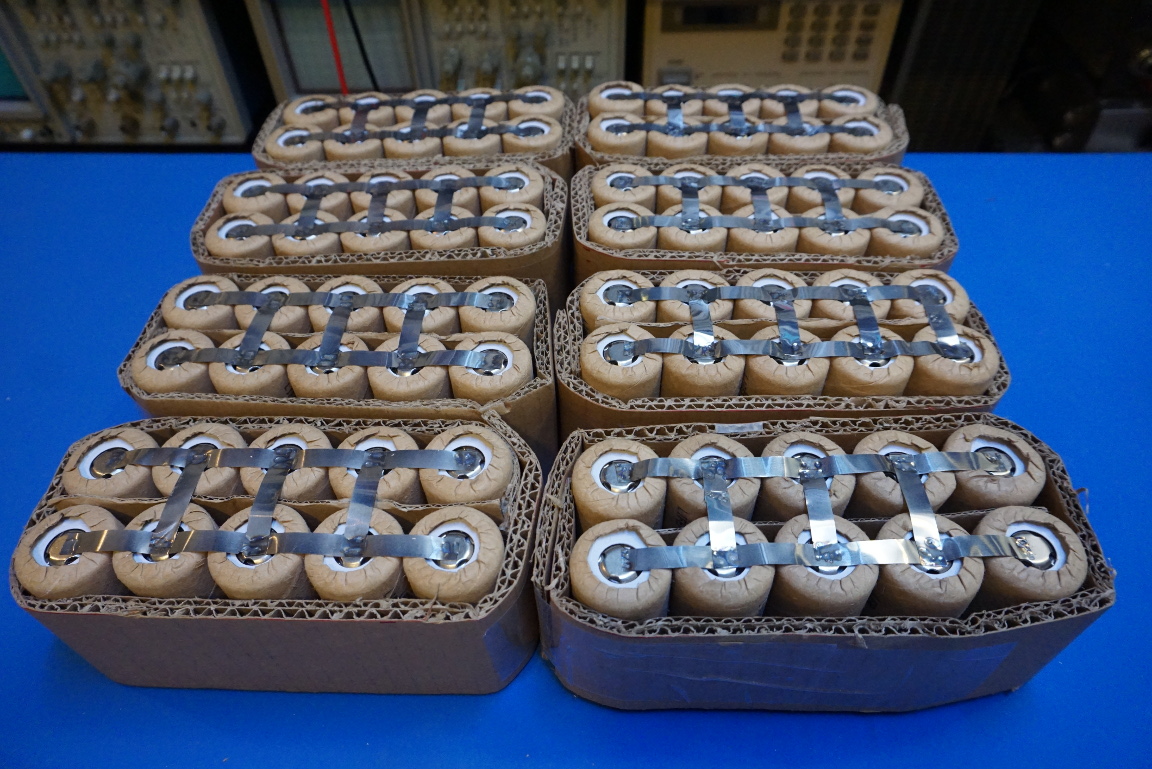
And here is a picture showing the eight 2×5 cell groups.
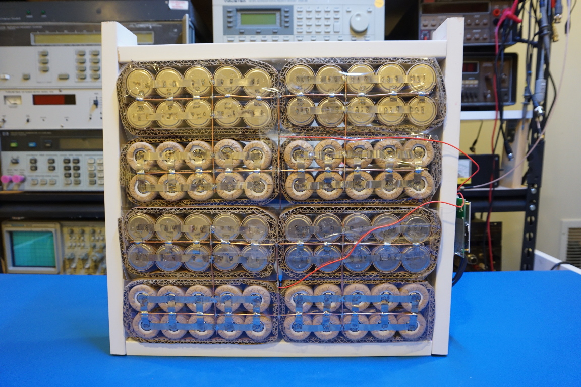
In the pictures below you can see what the final battery bank looks like after all the groups are wired together and the BMS added. As I mentioned in my previous post, I had to modify the BMS board so it can be used to balance the 110Ah battery bank.
I decided to solder these groups together using 8AWG copper wires instead of further welding them together. And for the positive and negative terminals, I soldered three 8AWG wires spaced across the entire length of the battery group to allow more even sharing of current. This is important as the maximum current through each terminal can be more than 100 A.
|
|
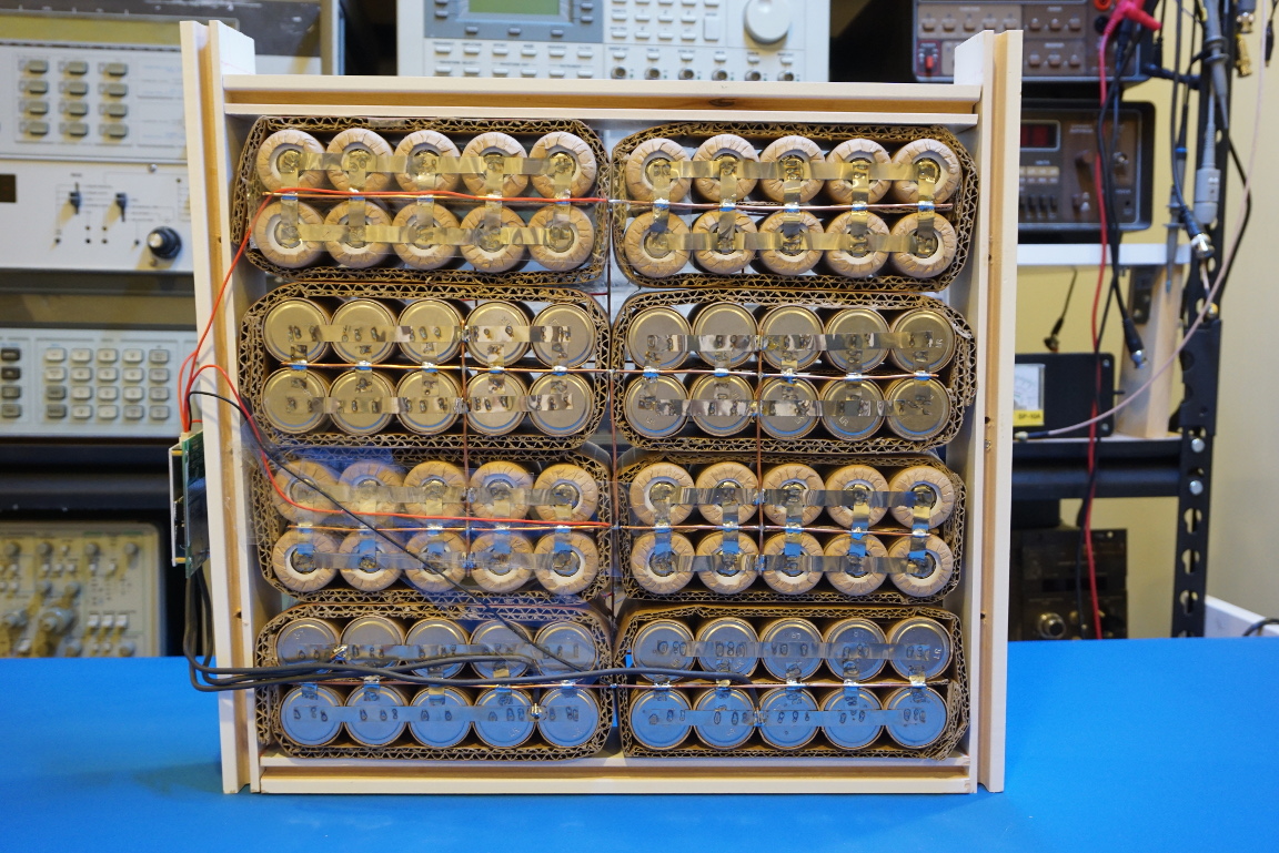
Here is a picture showing the BMS board, the negative battery terminal connector and the negative terminal used for charging.
Once I finished building the battery bank, I ran some load tests to ensure that the batteries and the BMS module are working properly. The video below shows me putting the battery bank through its paces.

