This topic is nothing new and there are already quite a few good articles on the web on this. But I thought I would try to provide a more comprehensive view on this issue and give a few concrete examples on how to filter out the electrical noise from motors in your circuits.
DC motors, especially brushed motors tend to generate a lot of noise (both acoustical and electrical), and the electrical noise can interfere with RF circuits and even logic circuits if not isolated properly, leading to erratic behaviors. This kind of noise-induced erratic behavior can sometimes be very hard to trace and debug.
The electrical noise generated by a DC motor falls into two categories: Electromagnetic interference (RF interference) and the electrical noise generated on the power rail.
Suppressing RF interference
The RF interference can couple into other portions of the circuit and cause circuit malfunction and performance degradation. If your project uses RF data link for instance, the motor induced RF noise can significantly decrease the usable RF range.
The level of RF interference is dependent on a few different factors: for instance, the type of the motor (brushed or brushless), driving waveform and load can all impact the severity of the RF interference. Typically, brushed motors generate more RF interference than their brushless counterparts. But the design of the motor, regardless of the type, also affects the RF leakage greatly. A small cheap toy brushed motor can sometimes generate magnitudes more RF interference than a carefully designed more powerful motor.
To reduce the level of RF interference, motors should be placed as far away from sensitive circuits as physically possible. Motor’s metal casing typically provides enough shielding capability for reducing the over-the-air RF interference, but an extra metal enclosure should provide much better RF interference reduction capability. It is important that in either case, the metal casing (either the motor casing or the metal enclosure) should be properly grounded (e.g. via ground strap at a single point).
The RF signals generated by the motor can also be coupled into the circuit, which forms what is known as the common mode interference. This type of interference cannot be eliminated by shielding, but can be reduced effectively via a simple LC low-pass filter. You can find a couple of examples in the next section.
Reducing Other Electrical Noises
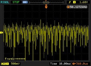
Another source of electrical noise comes from the power rail. Since power supply has a none-zero internal resistance, the none constant motor current flow during each rotation period would translate into voltage ripples across the power terminals. The following oscilloscope waveform capture shows the noise at the battery terminal when a small toy motor is powered via 4 AA Ni-Mh batteries with no filter added.

As you can see, the noise level is quite severe and the noise Vpp reached more than 3 Volts at times, which is more than enough to cause logic gates malfunction. And this kind of noise is likely to affect the performance of Op Amps and other analog circuitry as well.
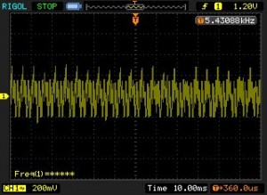
With a simple LC low-pass filter (100nf capacitor, 10mH choke for instance), the waveform improved somewhat, but the noise signal is still noticeable at around 0.5V Vpp:

Keep in mind that the above captures were taken using newly charged batteries. The noise level will likely be progressive worse as batteries discharge due to the increased internal resistance.
To further reduce the electrical noise, further filtering at the power source is needed. Typically, this is done by adding a larger capacitor (e.g. 1000uF and above) across the power terminals to lower the effective resistance of the power supply and thus improve transient response.
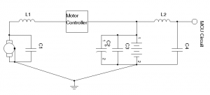
The following schematics show a couple of typical circuits for filtering out motor electrical noise.
The first filtering scheme is suited for uni-directional motor driving circuit. And the second one is suited for bi-directional motor driving circuit.

In bi-directional scenario (e.g. using an H-Bridge), two sets of LC filters should be used as the power to the motor is essentially center tapped.

The values for the inductors and capacitors used in the filters can be varied experimentally to achieve the best results. But in general, the capacitors on the motor side are several hundred nano-farads and the inductors are several milli-heneries. Higher order LC filters can further improve the noise-filtering performance but are rarely necessary.
Preventing Ground Loop
In the schematics shown above, please pay special attention to the grounding location. It is important to have the ground tied to a common place which is as close to the power supply source (i.e. the negative terminal of the battery) as possible. This grounding practice is especially important when there are other sensitive electronics component (e.g. MCUs, analog circuits) in your projects as the noise induced in the ground loop by the ground current can be significant if not taken care of properly.
If it is not possible to ensure a single grounding location, you should at least have the multiple subsystems’ (in this case motor system and the MCU circuits) grounds tied at a single point as close to the negative power terminal as possible. And within each sub system, make sure that the ground plane’s impedance is as low as possible.
With sufficient shielding, filtering and correct grounding practices the electrical noise generated by an electric motor can be reduced to a level that is low enough for even the most sensitive circuits.

