I bought a couple of Peltier cooler modules on eBay a while ago for some experiments. Of course, as I expected the quality of those cheap modules were pretty poor. After a couple of hours of continuous operation, both modules failed. So I decided to take a look to see if they could be repaired.
The failure mode I encountered was an open circuit, which probably means that either the module had failed entirely or the wire contacts went bad under high current operating condition.
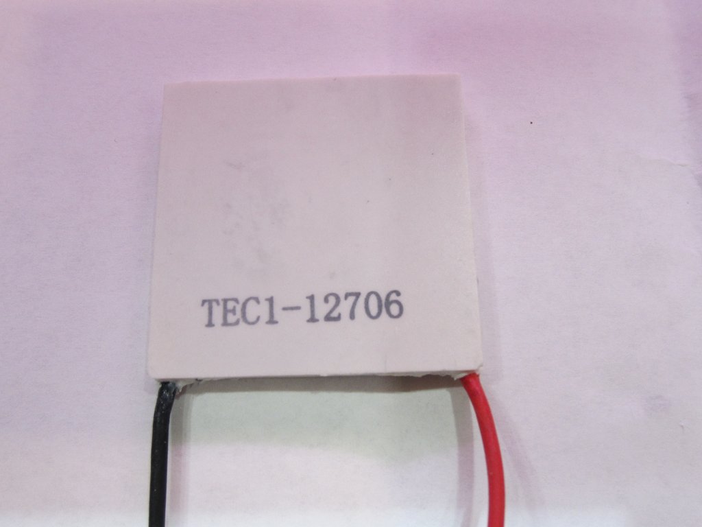
The modules I had were TEC1-12706 (12V 6A 72W) (see picture below). After taking them off the heat sinks and cleaning off the thermal grease I could not see any obvious sign of failure. So I decided to grind away the heat resistant silicone seal along the edges and take a closer look inside.
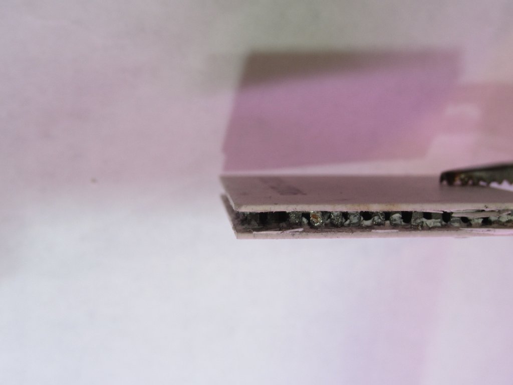
A typical Peltier module is constructed by placing highly doped p-type and n-type semiconductors in an alternating pattern to maximize the thermalelectric effect (the internal construction is illustrated here). So it is basically just a large package of P/N junctions connected in parallel. After removing the silicone filler, you can see the internal structure of a Peltier device. In the picture below, you can see the corner where the wire was originally bond at. One of the bond wires seemed to be open (the resistance between it and the neighboring P pallet and N pallet is near infinite) so I decided to take off the wires and reattach them.
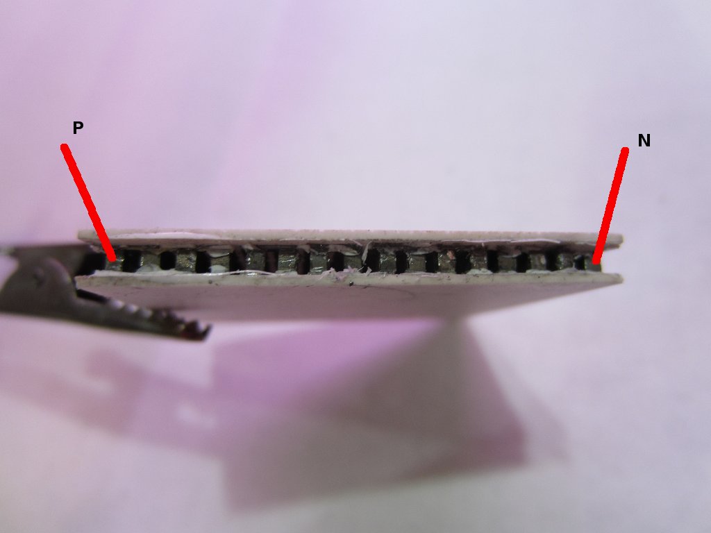
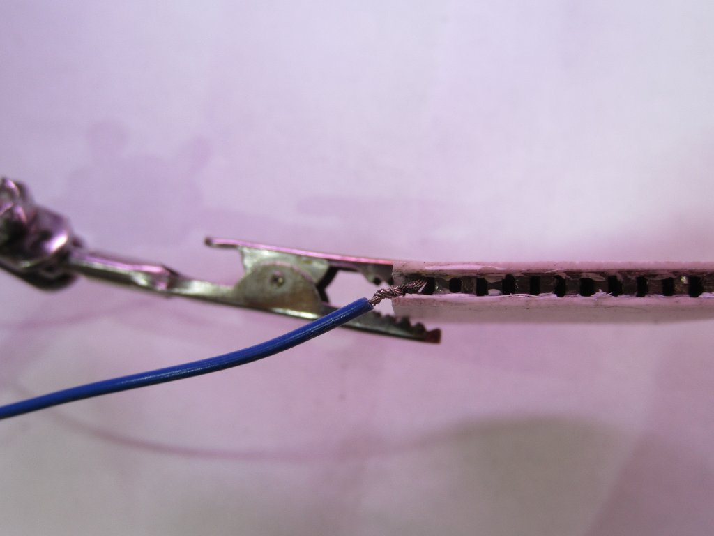
The P/N pallets in most of the Peltier devices are arranged in such a way that the outer-most pallets are of the opposite type, so basically all I needed to do is to attach two wires to the two points shown below:
These semiconductor pallets cannot be soldered with the standard soldering procedure, so the wires must first be firmly wrapped and then preferably be held in place using some conductive epoxy.
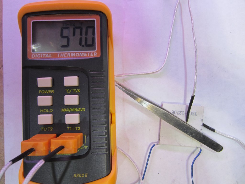
Now, it is fixed! (the picture below shows the temperature difference between the two surfaces when 3V was applied)