A couple of weeks ago I did a teardown of HP 6181C — a precision DC current source made in the late 70’s and early 80’s. This time around, I am going to show some pictures of an HP 6113A precision DC power supply and do a basic calibration using my Keithley 196 multimeter.
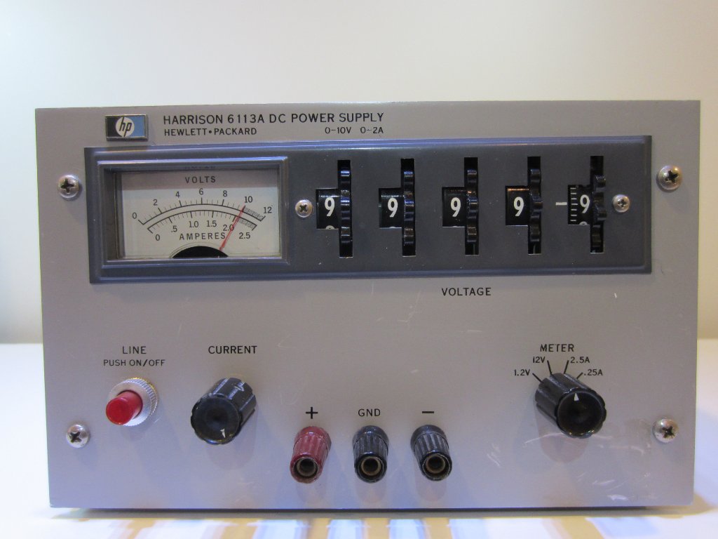
I bought this HP Harrison 6113A DC power supply on eBay a while ago. This series of precision power supplies were made way back in the late 60’s and early 70’s. It consists the following models: 6110A (0-3000V, 0-6mA), 6111A (0-20V, 0-1A), 6112A (0-40V, 0-500mA), 6113A (0-10V, 0-2A), 6116A (0-100V, 0-200mA). Among these five models 6113A has the highest output voltage resolution (100 µV). Even by today’s standard, this specification is still quite impressive and can only be found on some of the most expensive power supplies.
|
|
Don’t confuse this model with 6114A. HP 6114A (see discussions and pictures on EEVBlog) is a slightly more advanced and often most sought after precision power supplies. Arguably, 6114A has more integrated circuitry and offers higher voltage range and more standard features (e.g. precision current setting), but it usually sells for significantly more than a 6113A. Also, if you take a look at the specifications comparison (taken directly from the service manuals), you will find that 6113A offers slightly higher voltage output resolution, smaller drift and better temperature stability. Of course, if budget allows you might still want to pick up a 6114A since it’s output voltage is adjustable all the way up to 40V, making it a more versatile precision lab supply compared with 6113A.
| 6113A | 6114A | Range | 0-10V, 0-2A | 0-20V 2A, 20-40V 1A |
| Load Regulation | 0.001% + 100µV | 0.0005% + 100µV |
| Line Regulation | < 0.001% | 0.0005% + 40µV |
| Ripple and Noise | < 100µV (peak to peak) < 40µV RMS | < 100µV (peak to peak) < 40µV RMS |
| Temperature Coefficient | 0.001% + 10µV/degree C | 0.001% + 15µV/degree C |
| Drift (8 hour) | 0.01% + 100µV | 0.015%+15µV (potential meter set to 0), 0.015% + 100µV (non-zero) |
| Output Voltage Resolution | 100µV | 200µV |
| Output Voltage Accuracy | 0.1%+10µV | 0.025%+1mV |
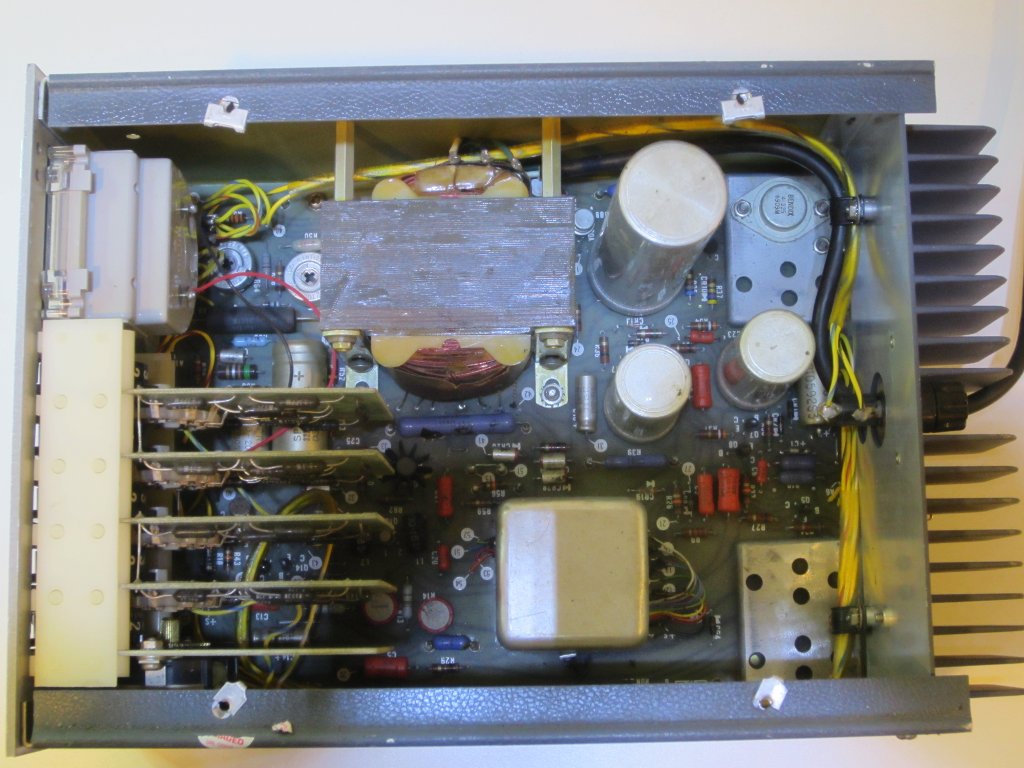
One of the key reasons HP 6113A offers such excellent temperature coefficient and low drift is due to its oven controlled precision voltage reference. In the picture below, you can see the metal can oven under the power transformer. The oven draws about 20W during operation, which is quite significant considering the entire power supply is only rated for 20W. But for a precision power supply, efficiency is far less of an issue.
Upon taking off the top cover, the first thing I noticed is that the the inside of 6113A is rather barren compared to that of 6114A. All the active components are on the single-sided main PCB that sits at the bottom of the case. This isn’t entirely surprising as the accuracy and precision of the unit is mainly achieved using the oven controlled precision voltage reference and precision low temperature coefficient resistors. As I mentioned last time, the main reason I like these decades old equipment is that they were all built with discrete components and no proprietary ICs were used. This means that they can be easily fixed with the readily available components if service is needed.
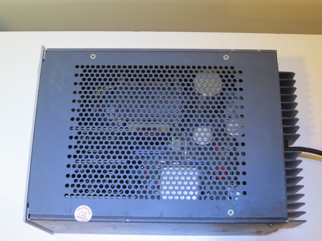
One thing interesting I noticed is the placement of the power transistor. The power transistor is mounted at one end of the heatsink, and there are three other empty mounting spots not used presumably for other models. This mounting position is not the most efficient one, but probably doesn’t matter much as the maximum power dissipation of the power supply is only 20W. Clearly, the huge heat sink at the back is an overkill for this particular model.
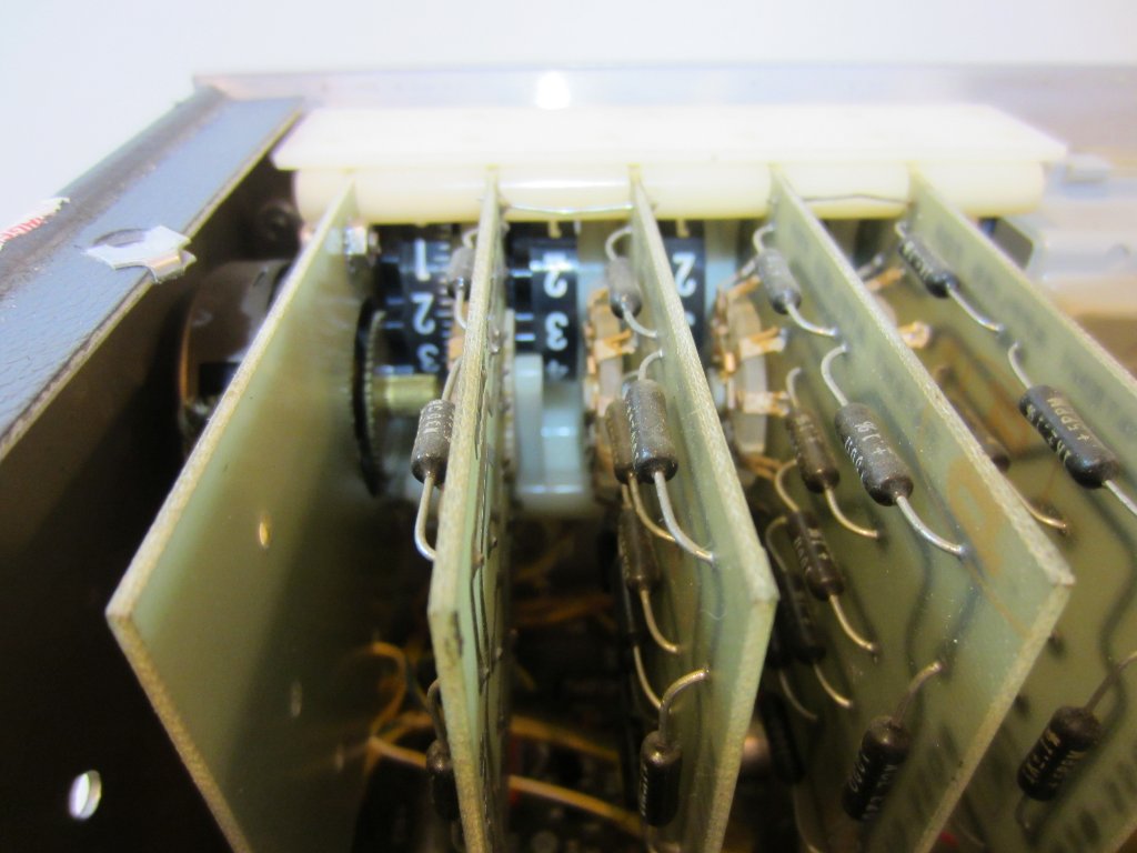
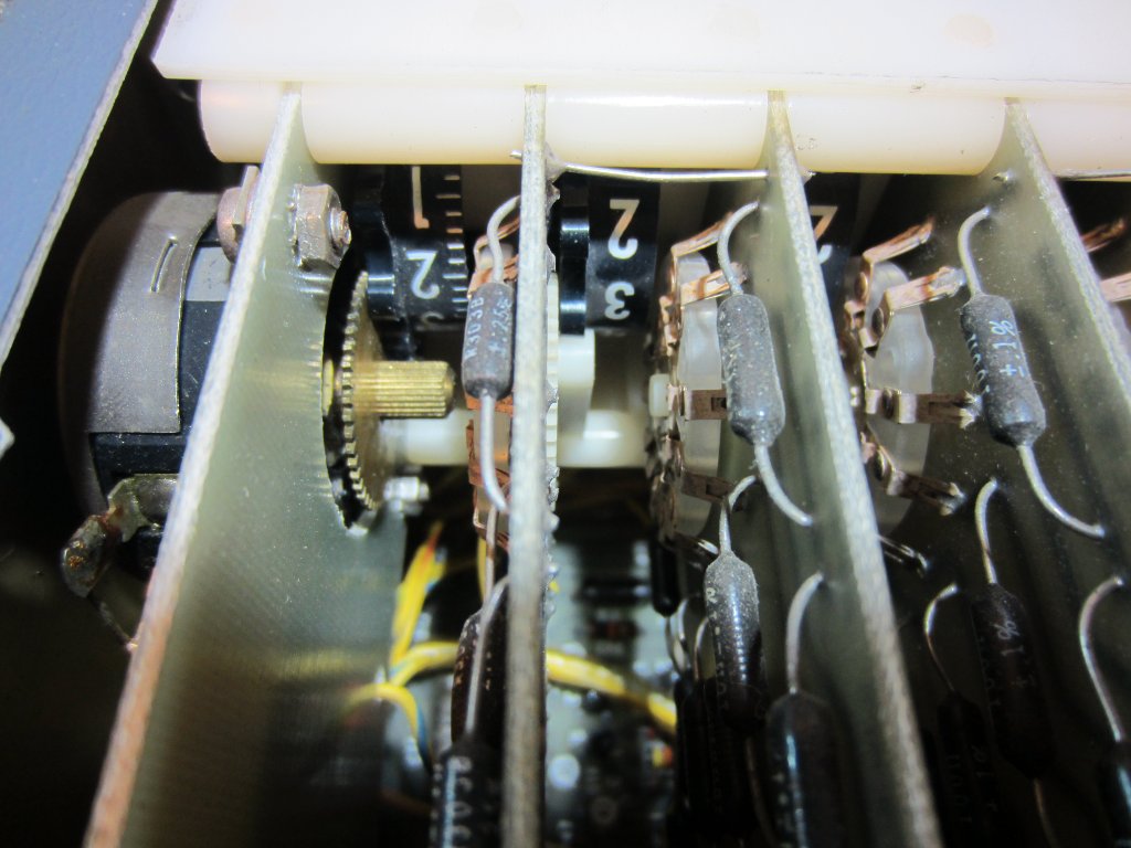
Below are two pictures of the voltage setting mechanism. These vertical boards are essentially precision rresistor voltage dividers. The first four decades are built with 10-position rotary switches and the least significant digit is adjusted via a single turn potentiometer. Recall that the specified minimum voltage resolution is 100µV, but in practice, the minimum achievable voltage resolution is likely to be much higher (50µV is easily achievable) with this potentiometer. I suspect if replaced with a multi-turn potentiometer, the voltage adjustment resolution can be increased further.
One potential issue of these mechanical range switches is that the contacts do get dirty over the years and proper cleaning is recommended to ensure that the contact resistances remain low and thus do not affect the overall accuracy of the voltage setting.
|
|
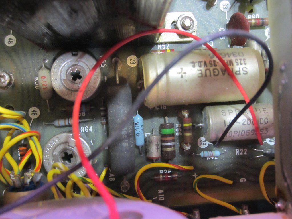
Because the specs are mostly guaranteed by the use of precision resistors, there are only very few adjustable components. In the left picture below, there are two large trim-pots which are used to adjust the panel meter full range in either voltage or current mode. They only affect the display accuracy and not the accuracy of the power supply itself.
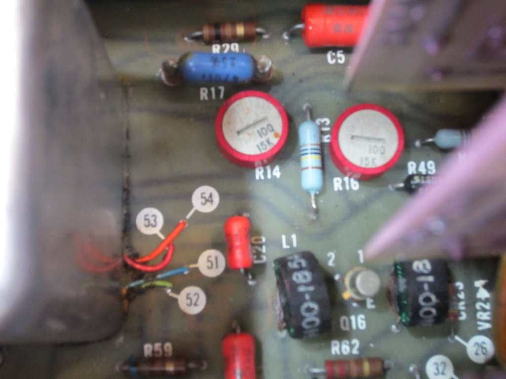
The two red trim-pots (R14 and R16) on the right are the only ones affect the actual voltage and current setting values. R14 is used to calibrate the zero-crossing voltage (in current mode) and R16 is used to fine-tune the output voltage.
|
|
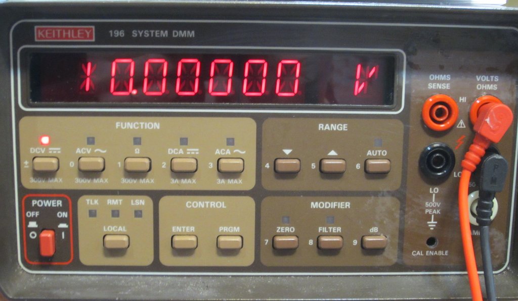
When I got the unit, it was still within spec according to my Keithley 196. It was probably last calibrated a couple decades ago but those precision resistors are very stable and rarely go out of tolerance. Since the resolution of Keithley 196 is 100 times better than 6113A, I thought I would re-calibrate the power supply so that it matches the meter readings. I carefully adjusted R16 with the supply set to 10V output until the meter reading was 10.00000V.
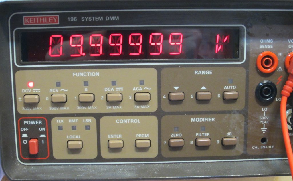
It is actually quite difficult to adjust the trim pot to get the the exact voltage reading because R16 only has a single turn. I may replace R16 with a ten-turn precision trimmer down the road. Anyway, this exercise was also to see how much this power supply drift over time. So after it was calibrated, I left the power supply on for a couple of hours and then measured again. The reading was 9.99999V, which was virtually unchanged. But this was somewhat to be expected from a precision voltage source in a climate controlled environment.
|
|
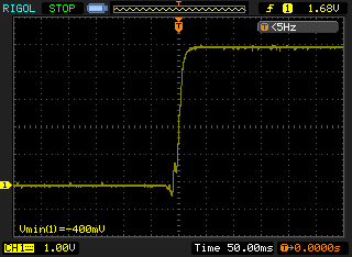
Finally, I took a single-shot oscilloscope capture of the power-on characteristics. The output voltage is set to 5V. As you can expect, the power on curve is pretty smooth (the noise on the trace is due to other devices connected to the main).