One way to extend the resolution of a digital-to-analog converter (DAC) is by employing a sigma-delta converter in software. The main disadvantage of such approach is the slow speed. Alternatively, we can use some extra hardware to extend the usable resolution of a DAC. In this post, I will illustrate one such method to extend an 8-bit DAC to 16 bits using a digital potentiometer.
So why do we want to extend the resolution of a DAC at the first place? Well, one of the key reasons is to lower cost. A 8-bit DAC usually costs less than a dollar, whereas a 16-bit DAC can easily cost ten to twenty times more. Fortunately, with the help of a potentiometer we can make a high resolution DAC out of a low resolution one.
The basic principle of this approach is illustrated below:
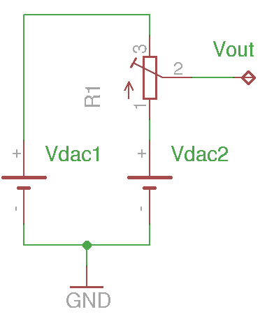
Suppose we have two DACs and they are set to output two different voltages. The final output voltage can be adjusted continuously between the two discrete output voltages via the potentiometer:
\[V_{out}=V_{DAC2} + (V_{DAC1} – V_{DAC2}) \frac{R_{21}}{R_{31}}\]
If we change the two DAC output voltages in lock steps (e.g. by 1 LSB) and replace the potentiometer with a digital one, the number of bits at the output is effectively the sum of the DAC resolution and that of the digital potentiometer. So we can obtain a 16-bit conversion accuracy with an 8-bit DAC and an 8-bit digital potentiometer.
In practice, it is a bit more complicated. Since the error characteristics for different DACs (e.g. differential/integral non-linearity, full-scale/zero-scale error, etc.) are likely to be different, Vdac2-Vdac1 are not guaranteed to be the resolution of the DAC. Luckily, if we select a multi-channel DAC such as LTC1665 and TLV5620, the non-linearity errors among the different channels are likely to be quite comparable and we can hand-pick channels that have near-identical zero-scale and full-scale errors. More importantly, because the DAC channels are on the same die, their temperature characteristics are also identical. Note that it is important to closely match these two DACs as the matching accuracy largely determines the overall accuracy of the bit-extended DAC.
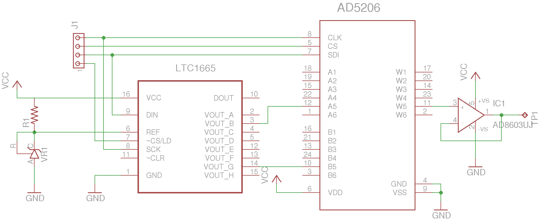
The schematic below is my experimental circuit. Here I used a LTC1665 8-bit 8-channel DAC (see my previous article on interfacing with Arduino) and a 8-bit 6-channel digital potentiometer with a nominal resistance of 10K (only a single channel is needed). LTC1665 is not a precision DAC and there are quite some variations among different channels. After some measurements, I picked channel 2 and channel 5 as they produce nearly identical voltage outputs between 0 and 255. Because the current flowing through the potentiometer is in the sub-µA range, A precision rail-to-rail opamp (AD8603) is added as a voltage follower to ensure the accuracy of the voltage divider.
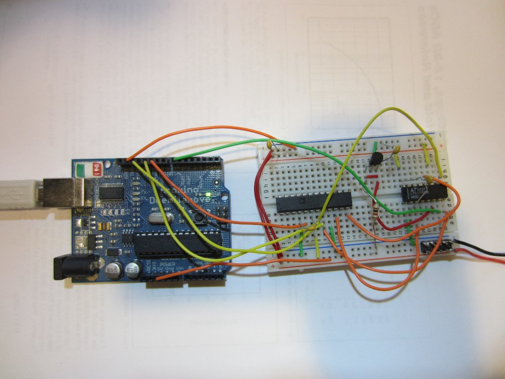
Here is a picture of the circuit built on a breadboard for testing purpose (AD8603 was not shown in this picture). Each chip is decoupled with a 100 nF capacitor.
The program below sets the DAC output voltage to 6.3V (corresponding to DAC inputs half way between 64 and 65). Because the digital potentiometer has an additional 8 bits of resolution, the minimum output voltage resolution (approximately 38 µV) is 1/256th of the DAC resolution (approximately 9.8 mV).
#include <SPI.h>

const int CSPOT = 10;
const int CSDAC = 7;

void setup() {
    pinMode(CSPOT, OUTPUT);
    pinMode(CSDAC, OUTPUT);

    SPI.begin();

    //given a reference voltage of 2.5V
    //each DAC step is 9.766 mV
    //DAC2 is set to 0.6250V
    //DAC5 is set to 0.6348V
    setDAC(2, 64);
    setDAC(5, 65);

    //set channel 5 to the middle
    //so the output at the wiper is 0.6299V
    setPot(4, 128);
}

void loop() {}

//AD5206
void setPot(int address, int value) {
    digitalWrite(CSPOT,LOW);
    SPI.transfer(address);
    SPI.transfer(value);
    digitalWrite(CSPOT,HIGH);
}

//LT1665
void setDAC(int address, int value)
{
    int h = address << 4 | value >> 4;
    int l = value << 4;
    digitalWrite(CSDAC,LOW);
    SPI.transfer(h);
    SPI.transfer(l);
    digitalWrite(CSDAC,HIGH);
}
Final Thoughts
In some DACs the outputs cannot source any current. In this situation, a large resistor (e.g. 100K) needs to be connected between the lower output node and the ground to provide current returns from the potentiometer between the two outputs.
Because the voltage difference between the two consecutive DAC input codes is small, using DACs with a resolution higher than 8 bit is not recommended as the mismatch between different DACs are likely to affect the overall accuracy much more severely due to the finer voltage resolution. Also, the current flowing through the potentiometer will be even smaller and the input impedance of the opamp will likely affect the voltage divider accuracy.
So in practice, this method of extending an DAC resolution is best suited for DACs with lower resolution (e.g. <= 8-bit) and is rarely used to extend the overall resolution beyond 16 bits.

