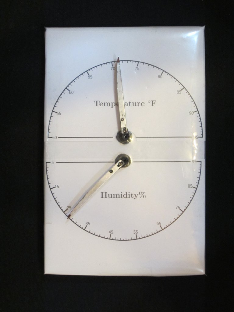
It seems that you can’t visit to a microcontroller website without seeing a digital thermometer/hygrometer build of some kind. After all, it is pretty easy to build and at the same time quite useful as well. In this post, I will show you yet another thermometer/hygrometer build. But instead of using an LCD or 7 segment display for the output, I decided to go retro, using two “needles” to display the temperature and humidity readings instead.
And to make the project more fun, I did not use analog meters for the output but chose to use two servos instead. The temperature humidity sensor I used is SHT21 from Sensirion, the same sensor I used in my temperature logging project before. In that project, the temperature and humidity readings were sent over the network and displayed on my web server (you can see the current readings in my lab here).
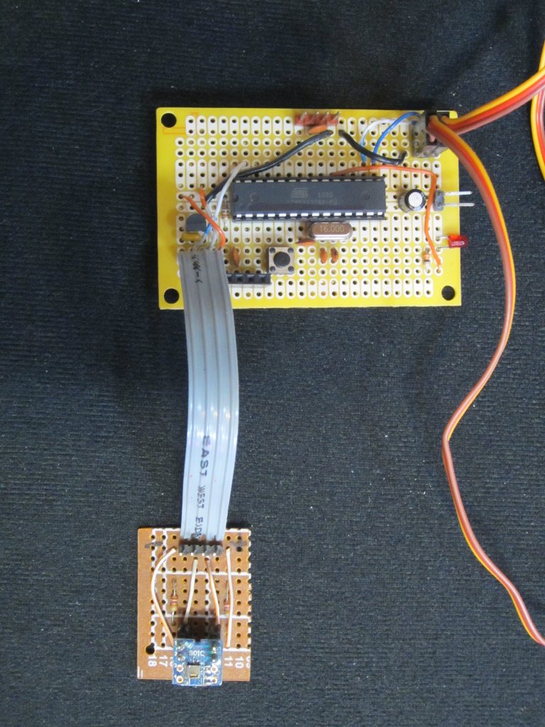
The pictures below show how everything was put together. The circuit itself is as simple as it gets. SHT21 is mounted on a breakout board and connected to the ATMega328p board via ribbon cable. The sensor is placed at some distance away from the MCU board so that the measurement is not affected by the heat dissipated by the MCU and it’s surrounding circuitry. Because SHT21 operates at 3.3V, an MCP1700 regulator is used to provide 3.3V voltage to the sensor and the MCU. The servos I used are MG90s but you can pretty much use any servos you have on hand. The servos are powered via the pre-regulated 5V power supply and are attached to digital pin 9 and 10 on the Arduino board.
|
 |
I used is from ModernDevice‘s SHT21 library to read the sensor. And the entire Arduino code listing is included towards the end.
For MG90S, the servo arm moves from 0 degree to 180 degree when the value passed into writeMicroseconds ranges from 600 to 2100 microseconds. Depending on the servos you use, the actual values may need to be adjusted.
Here is a short video showing how this display works:
|
View on YouTube in a new window |
The update rates were set to 0.5 second as in practice the environmental temperature and humidity do not change that rapidly. The movements of the temperature servo and humidity servo are also interleaved to lower the peak current requirement.
The measurable ranges are chosen to simply calculations. For example, the temperature range is from 50 degree Fahrenheit to 95 degree Fahrenheit spanning 45 degrees. Because the pulse width range is between 600 microseconds and 2100 microseconds for the servo arm to rote 180 degrees, each microsecond represent a 0.03 degree temperature change (i.e. (95-50)/(2100-600)). Similarly, for humidity display the range is chosen to be from 5% to 95% so that each microsecond represents a 0.06% humidity change (i.e. (95-5)/(2100-600)).
#include <Wire.h>
#include <Servo.h>
#include <LibHumidity.h>

LibHumidity tempSensor = LibHumidity(0);
double t, h;

Servo tempServo;
Servo humidServo;

void setup()
{
    tempServo.attach(9);
    humidServo.attach(10);
}

void loop()
{
    t =  tempSensor.GetTemperature() * 1.8 + 32.0;
    if (t < 50.0) t = 50.0;
    else if (t > 95.0) t = 95.0;

    int temp = 2100 - (int) ((t - 50.0) / 0.03);
    tempServo.writeMicroseconds(temp);
    delay(500);

    h =  tempSensor.GetHumidity();
    if (h < 5.0) h = 5.0;
    else if (h > 95.0) h = 95.0;

    int humidity = 600 + (int) ((h - 5.0) / 0.06);
    humidServo.writeMicroseconds(humidity);
    delay(500);
}
Here are the PGF files I created for creating the scales: scales.tar.gz

