In this blog post, I will show you how to build a 0 to 5.8 GHz tracking generator for the HP 8566B 100 Hz to 22 GHz spectrum analyzer using off-the-shelf components for under $100. Although this tracking generator is specifically designed for my HP 8566B spectrum analyzer, the method discussed below is applicable to pretty much any spectrum analyzer that has an LO output (typically the 1st LO).
A tracking generator, as its name implies, tracks the frequency of the spectrum analyzer’s sweeping oscillator (typically 1st LO) so that the tracking generator’s frequency output matches the center frequency of the bandpass filter in spectrum analyzer’s IF stage. Thus at any given moment, the spectrum analyzer sees the same frequency input as what it is currently sweeping at. The combination of a spectrum analyzer and a tracking generator is often referred to as a scalar network analyzer (SNA).
Tracking generators are very useful for measuring the frequency response of filters and amplifiers. In my previous blog post, I discussed how to perform this kind of measurements using the manual sweeping method, without using a tracking generator. Although there are some benefit sweeping through the frequency range manually, the obvious downside is the slow speed. Because of this, the manual sweeping method is only useful for characterizing devices with time-invariant frequency responses as a single sweep can take minutes to complete.
The basic principle behind a tracking generator is rather simple: the tracking signal can be obtained by subtracting the IF frequency from the LO output via a mixer. Take the base band (0 – 2.5 GHz) of HP 8566A/B for instance, the 1st LO output goes from 3.6214 GHz up to just above 6.1 GHz during each sweep. So if we subtract the 1st IF frequency (3.6214 GHz) from the 1st LO, we get our precise 0 – 2.5 GHz tracking signal.
John Miles at KE5FX documented his 2.5 GHz tracking generator build for the HP 8566A/B on his website. In his build, John used the mixer and automatic level control (ALC) circuitry from an HP 86222A RF plugin. And you can find a similar build by CuriousMarc using the mixer from an HP 83522A plugin for the HP 8350B signal generator.
If automatic leveling is not a primary concern (most of the time, leveling is not critical since almost all spectrum analyzers have builtin functionalities to calibrate and thus correct the leveling of the sweeping source), a tracking generator can be built using just a suitable microwave frequency mixer and a reference frequency that is determined by the frequency band in use. This approach is what I used for building my tracking generator.
Before going into more details, let’s first take a look at the different base and harmonic bands HP 8566B can operate under:
| Band | f1 (GHz) | f2 (GHz) |
| 0 | 0 | 2.5 |
| 1 | 2.0 | 5.8 |
| 2 | 5.8 | 12.5 |
| 3 | 12.5 | 18.6 |
| 4 | 18.6 | 22 |
The frequency ranges listed above are specified in HP8566B’s manual and are the typical frequency intervals for the harmonic bands during the default automatic sweeping (i.e. band unlocked, SHIFT+Q). Since the 1st LO can sweep between roughly 2 GHz and 6.2 GHz, the actual achievable range for each harmonic band is actually much wider. The following table lists the frequency ranges when each harmonic band is locked (SHIFT+t):
| Band | f1 (GHz) | f2 (GHz) | f1 (LO GHz) | f2 (LO GHz) |
| 0 | 0 | 2.5785999 | 3.6214 | 6.1999999 |
| 1 | 1.67860005 | 5.8785999 | 2.000000050 | 6.1999999 |
| 2 | 4.32140005 | 12.7213999 | 2.000000025 | 6.199999950 |
| 3 | 6.32140005 | 18.9213999 | 2.000000016 | 6.199999966 |
| 4 | 8.32140005 | 25.1213999 | 2.000000012 | 6.199999975 |
By examining the data above, you will notice that the IF for the base band is at 3.6214 GHz and for all the harmonic bands the IF sits at 321.4 MHz.
The base band (band 0) and the first harmonic band (band 1) are of particular interests, as the LO output can be used as the tracking generator output signal directly after subtracting the IF frequency without the need of harmonic mixing.
[adsense]
Choosing a Mixer
So a suitable mixer for our tracking generator should be able to mix signals in the entire LO range (2 GHz to 6.2 GHz) with either an IF frequency of 3.6214 GHz for the base band or an IF frequency of 321.4 MHz for the first harmonic band. Because the LO output from HP 8566B is greater than 5 dBm, a level 7 or level 10 mixer is suitable.
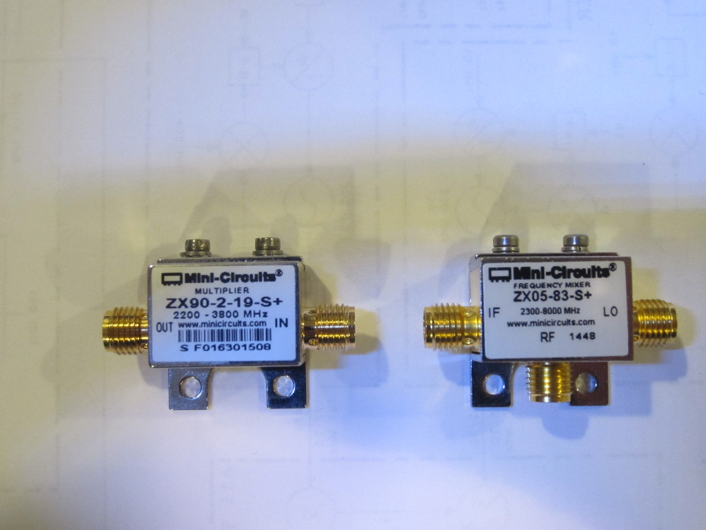
I ended up choosing Mini-Circuits’ ZX05-83-S+ 2300 MHz to 8000 MHz level 7 mixer as my work will mainly be dealing with frequencies under 2 GHz. This mixer has excellent performance in the 0-2.5 GHz base band for mixing the 3.6214 GHz to 6.2 GHz LO signal with the 3.6214 GHz IF. This mixer is relatively inexpensive, retails for less than $50. As you will see later, even though this mixer is not rated for RF signals as low as the IF frequency for the first harmonic band (321.4 MHz), it is still usable in the 5.8 GHz frequency band, but the performance does suffer suffer a bit.
If you need to work in the first harmonic band more often, you probably want to consider a wide band mixer such as Mini-circuits’ SYM-63LH+ level 10 mixer, which has a reasonable performance curve between 1 MHz and 6 GHz. It only costs slightly more than $10, but only comes in surface mount package.
For any other frequency bands (other than the base band and the first harmonic band discussed above) you will need to find a suitable subharmonic mixer for the desired frequency ranges, but it will likely be very pricey unless you can find a used one on eBay.
Choosing an RF source
An ideal RF source for the tracking generator should be phase-locked to the spectrum analyzer, this is especially important when the resolution bandwidth (RBW) used is narrow. It also should have sufficient output power (e.g. at least 0 dBm) so that the tracking signal is strong enough to provide adequate dynamic range.
There are a couple of solutions available. One is to get a PLL signal source that is capable of generating the 3.6214 GHz signal for the 0 – 2.5 GHz range and/or the 321.4 MHz signal for the 1.68 GHz to 5.68 GHz range (band locked to the first harmonic band). Such phase locked oscillators are widely available on the used market and can be had for less than $30. If you only need to use a relatively high RBW, then the oscillator does not even need to be phase-locked to the spectrum analyzer clock, as long as the oscillator is stable enough.
Alternatively, you can use a signal generator or synthesizer to generate the desired frequency. As a bonus, most signal generators can be phase locked to an external clock source. Since I already have a synthesized RF signal generator (HP 8642B), I chose to use that to generate the required frequency. Of course, since HP 8642B only goes up to 2.1 GHz whereas the signal required is at 3.6214 GHz. So I used a Mini-Circuit frequency doubler (ZX90-2-19-S+) to get the required signal by doubling a 1.8107 GHz 10 dBm input signal.
This setup is not as ideal as using a proper 3.6214 GHz signal source however as there will be some fundamental frequency leak-through in addition to the higher harmonics generated by the multiplier. Also, due to the conversion loss of the frequency doubler and its maximum allowed input level, the strength of the output RF signal is only at around 0 dBm. Of course, this issue can be alleviated by adding in a cavity filter after the doubler and inserting an amplifier to further boost the signal strength before inputting into the mixer. But this would add considerable cost to the tracking generator. As is, this tracking generator is already quite usable.
LO Isolation
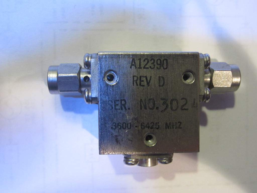
Although it is possible to connect the LO output directly to the mixer’s LO input, the reverse LO leakage will reduce the available dynamic range. So I decided to add an isolator between the LO output from the spectrum analyzer and the LO input to the mixer. I happen to have a Harris A12390 isolator on hand, it offers 20 dB isolation from 3.6 GHz to 6.4 GHz which covers almost the exact LO frequency range for the base band. Although from my experiment data shown later, the inclusion of the isolator only added marginal benefits. I suspect that adding a narrow bandpass filter centered at 3.6214 GHz would help as the output from the frequency doubler has a lot of unwanted signal components.
Alternatively, an attenuator in conjunction with a low gain amplifier could also be used to reduce the back feeding of the LO signal.
[adsense]
Putting It Together
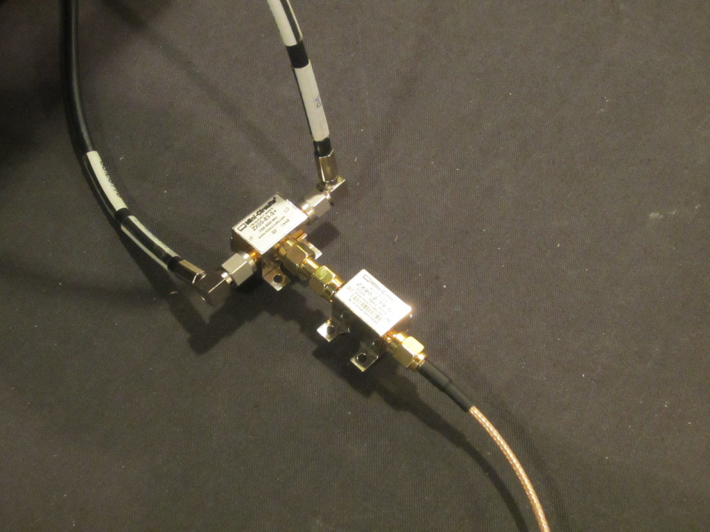
The diagram below shows the components used in my tracking generator: the mixer (ZX05-83-S+) takes signal from the 1st LO and mixes it with the 3.6214 GHz signal from the frequency doubler (ZX90-2-19-S+) and generates the 0-2.5 GHz tracking signal for the base band. The input to the frequency doubler is taken from my HP 8642B which is phase-locked to the HP 8566B.
![]()
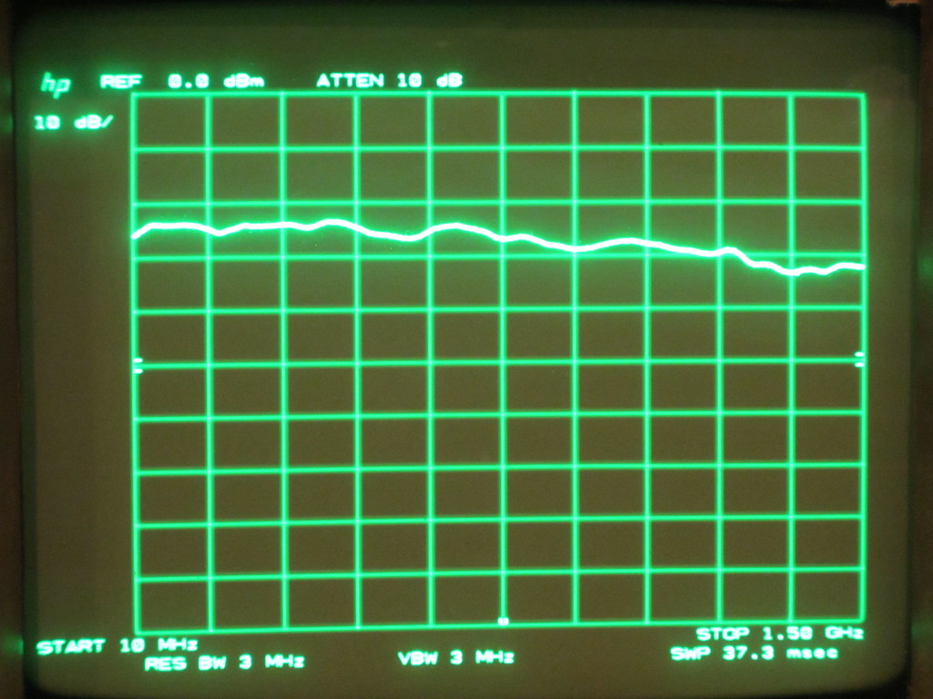
The maximum signal strength of the tracking signal is limited by the LO signal strength and the RF signal strength (the output from the frequency doubler). The frequency doubler used here limits the maximum input power to 10 dBm, and the output 3.6214 MHz frequency is just under 0 dBm. Adding the conversion loss from the mixer, the tracking signal is at around -7 dBm which still gives at least 25 to 50 dBm of dynamic range.
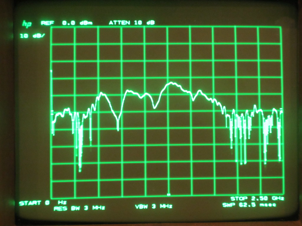
The quality of the tracking signal is actually quite good. It is reasonably flat considering that this is taken from the LO output directly, without using a leveling amplifier.
![]()
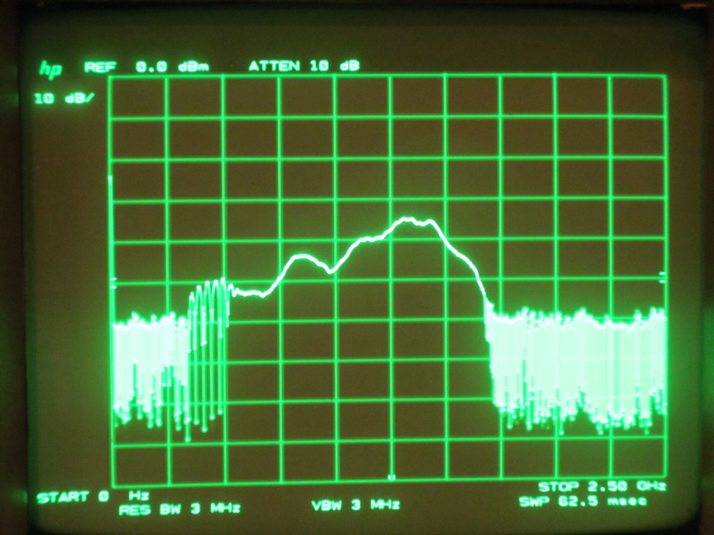
The picture to the left below shows the actual tracking generator components. The picture to the right shows the noise floor when the spectrum analyzer’s input is disconnected. The baseline noise floor is not as ideal as I had hoped. At between 1 GHz to 1.5 GHz there is a significant rise in the baseline noise and because of this we only get about 25 dBm of dynamic range within this frequency region.
As mentioned earlier, I believe this added noise can at least be partially attributed to the multiple frequency components in the multiplied signal. I will need to do a couple of comparison studies by either using a phase locked oscillator to provide the 3.6214 GHz signal directly or using a cavity bandpass filter centered around 3.6 GHz to see which method yields the best dynamic range.
|
|
|
The addition of the RF isolator (3.6 GHz to 6.4 GHz) does seem to have improved the performance a little bit, although not as much as I had thought. The picture to the left below shows when the isolator was taken out of the equation and the picture to the right below shows the measured noise floor without using the isolator. As you can see, the isolator seemed to have narrowed the noise in the “problematic” band quite a bit but only managed to reduce it by a few decibels in the 1 to 1.5 GHz region.
But this picture does suggest that you probably can do away with the RF isolator, which could reduce the BOM even further.
|
|
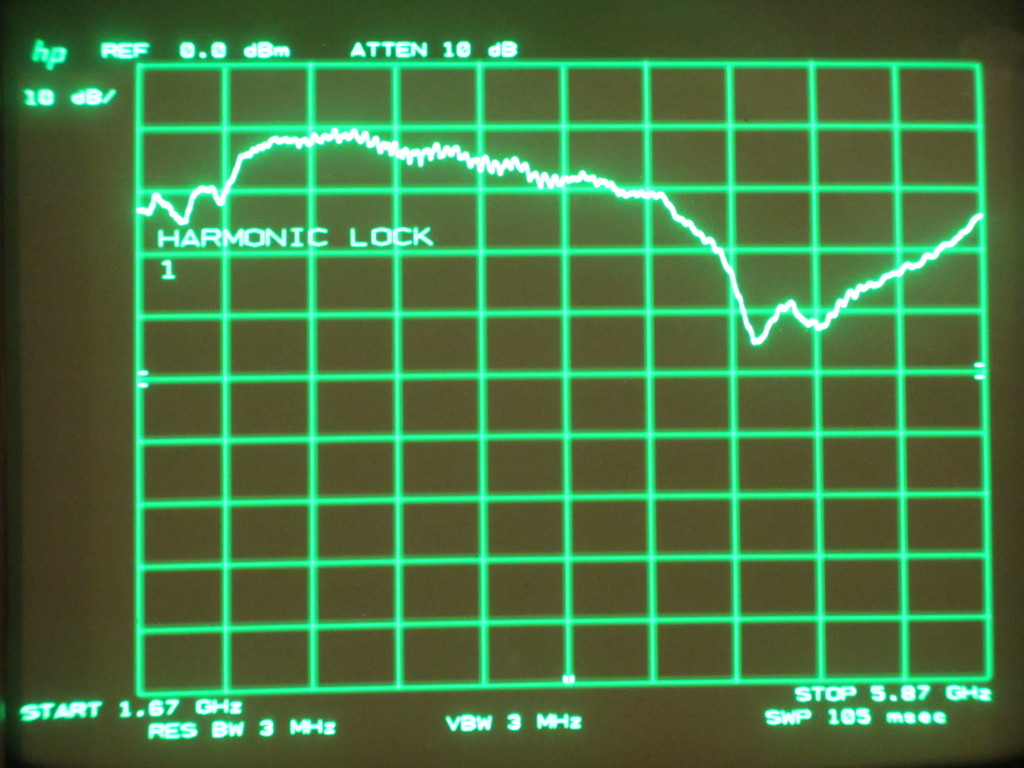
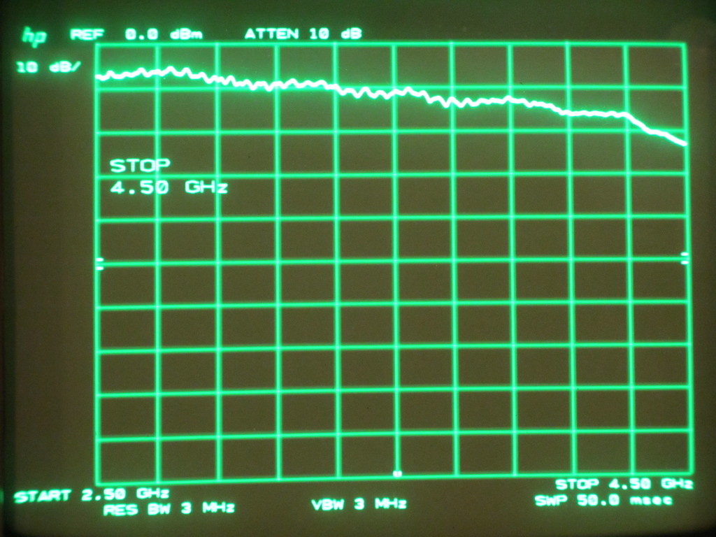
For the 1st harmonic band, a 321.4 MHz signal from the HP 8642B is coupled directly into the RF port of the mixer without using the frequency doubler. While the tracking signal’s strength varied wildly between 1.67 GHz and 5.87 GHz (with the 1st harmonic band locked), the performance is actually quite reasonable between 2 GHz and 4.5 GHz.
Note that for the first harmonic band the 321.4 MHz signal was adjusted to 10 dBm which was inputted into the mixer directly (as opposed to the 0 dBm signal via the frequency doubler in the base band), this additional power helps improve the dynamic range.
Since the mixer (ZX05-83+) used here is technically not rated for frequencies under 2.3 GHz (the IF for the harmonic band is only 321.4 MHz), the performance we see is actually quite good. Of course, you can always swap for a better spec’d mixer if you find yourself needing to characterize devices in the first harmonic band more often. I think you should see additional performance improvement with a properly rated mixer.
|
|
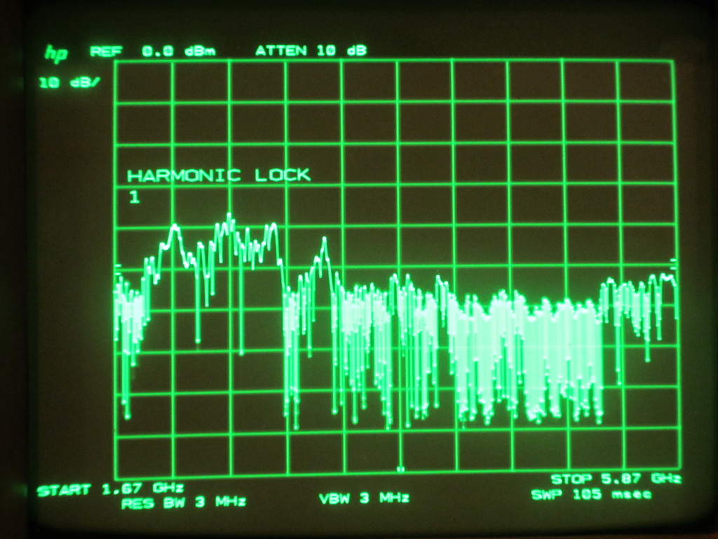
Here is a picture showing the noise floor of the tracking generator in the 5.8 GHz harmonic band.
[adsense]
Experiments
All the experiments I did in my previous blog post using the manual sweeping method can now be done with the tracking generator instead.
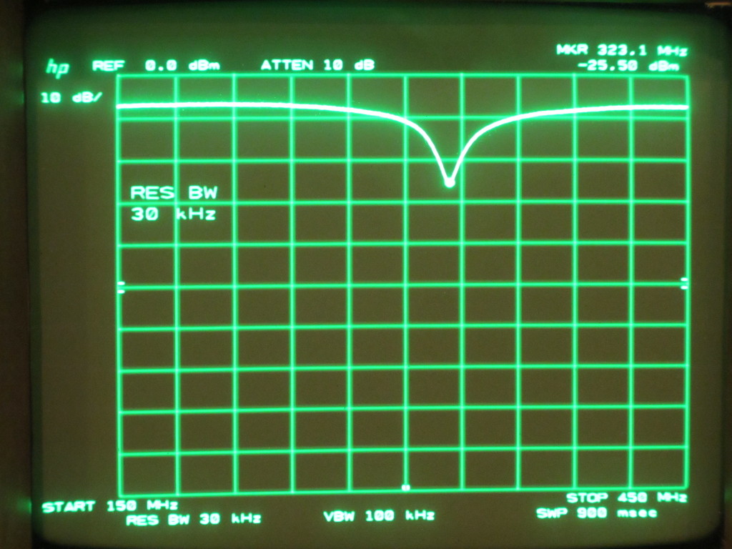
The first experiment below shows the characterization of an LC filter. Because the tracking generator’s output is very flat between 150 MHz and 450 MHz, no trace adjustment was made before the expeirment:
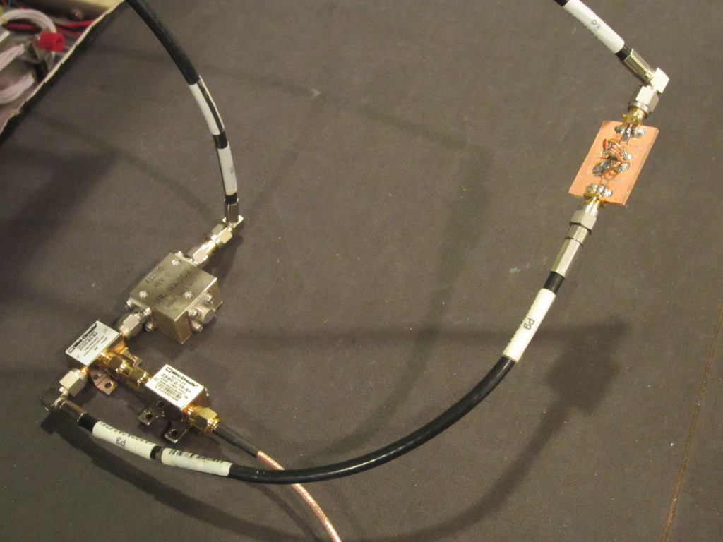
Here is the measured result. As you can see from the screenshot below, the resonant frequency of this particular LC filter is at 323.1 MHz.
The next experiment shows the gain-bandwidth characterization of an ADL5536. ADL5536 is a 20 MHz to 1 GHz IF gain block with a fixed gain of 20 dBm.
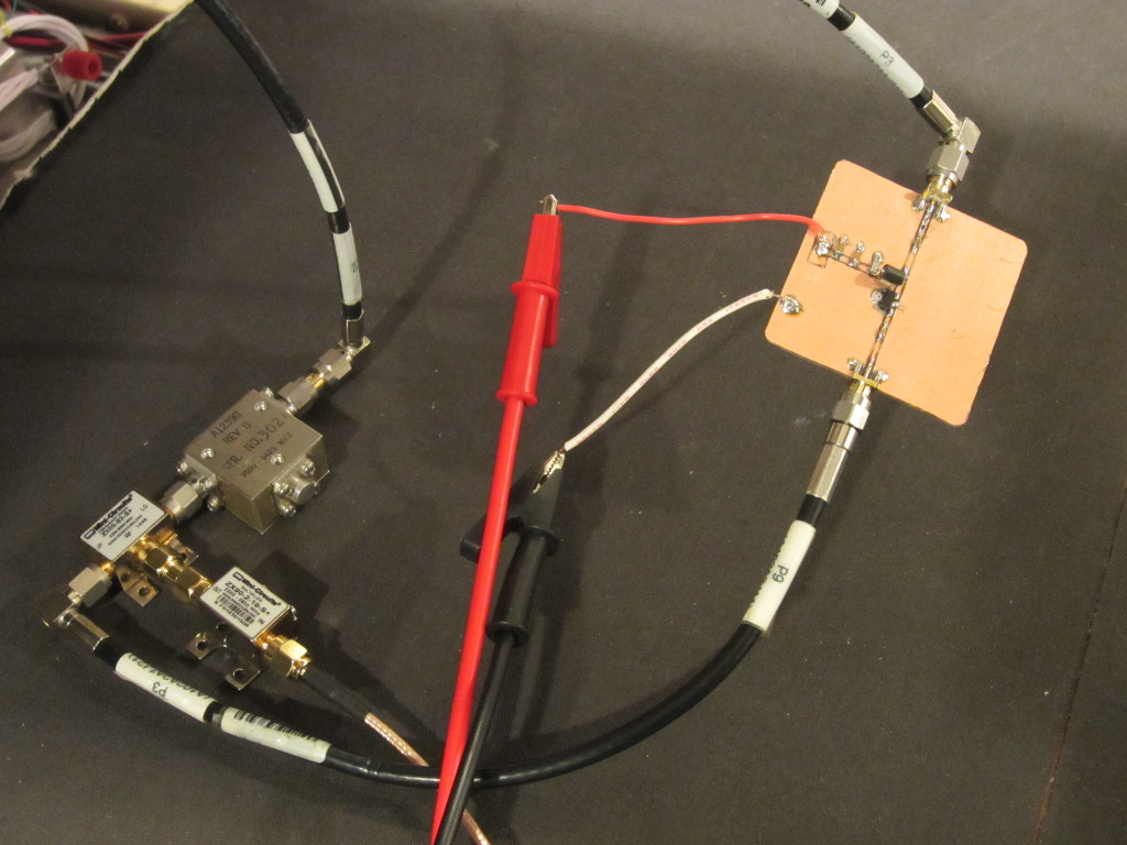
For the measurement, the baseline is lowered to just below -40 dBm (by lowering the RF input into the mixer) and trace arithmetic was used to normalize the baseline between 10 MHz and 1.5 GHz. This is condition is slightly different than what I used during my video demonstration.
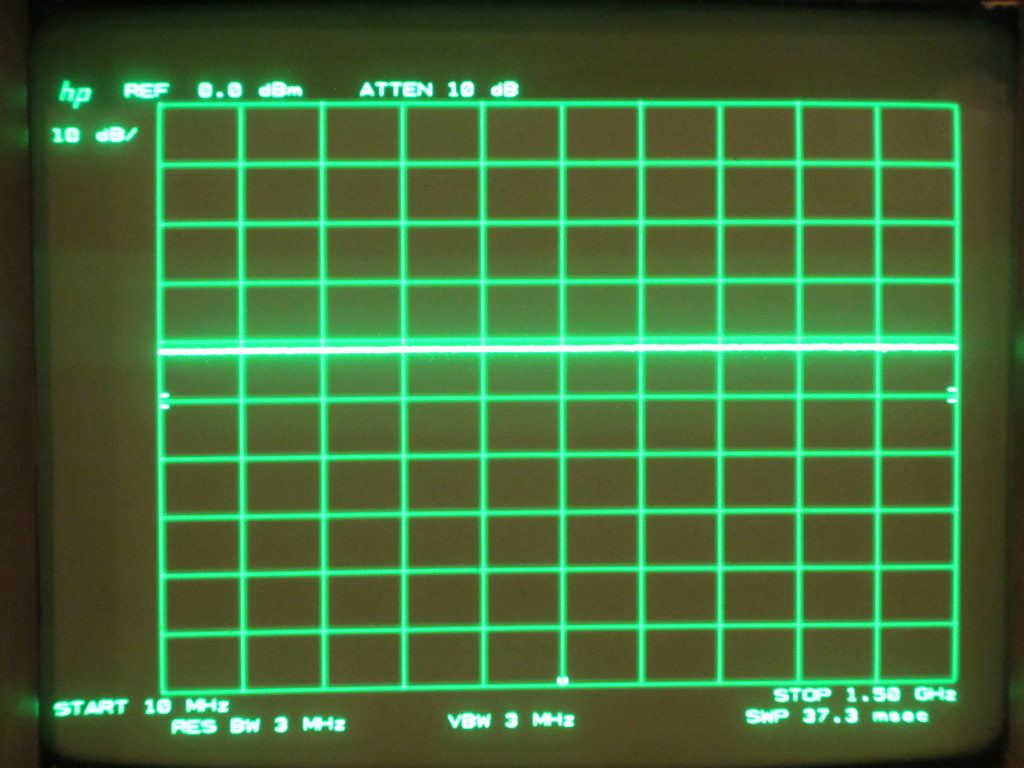
And the picture below shows the output level from the RF amplifier between 10 MHz and 1.5 GHz. There are some losses due to the coax used, but the shape of the curve is largely in line with what is specified in the datasheet. And as you can see, the gain of this amplifier rolls off very gradually as frequency increases and thus this amplifier could be used all the way up to at least 1.5 GHz. Of course, at the higher frequency end, the gain is limited to just around 10 dBm.
Final Thoughts
While the work done here is for the HP 8566B spectrum analyzer, the same method can be used to build tracking generators for virtually any spectrum analyzers with an LO output. As I illustrated, a very basic tracking generator can be built from off-the-shelf components for less than $100. Additional components (e.g. RF isolators, bandpass filters, leveling amplifiers and subharmonic mixers etc.) can be added to improve the tracking generator performance further.

