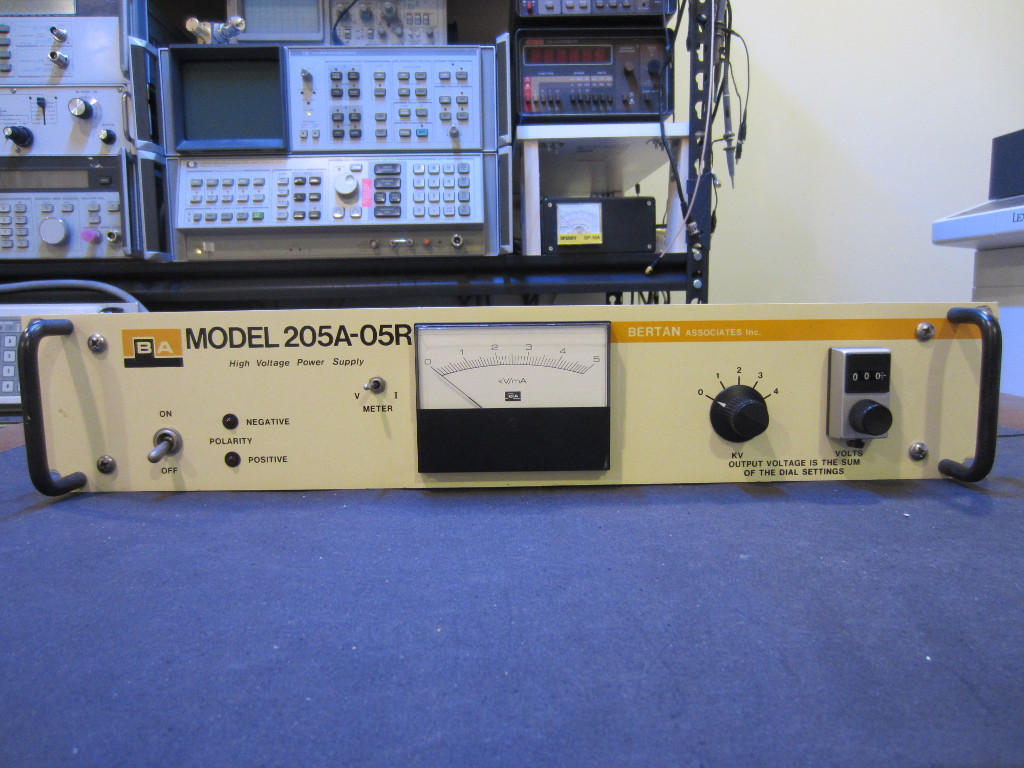
I got a non-working Bertan 205A-05R 5kV high voltage power supply and did an attempted repair video a while ago (see video towards the end). But I forgot to post my teardown pictures somehow. So here we go, better late than never.
Bertan 205A-05R is a 0-5 kV 5mA high voltage power supply. It is entirely analog, the voltage can be set via the front panel range switch (kV) and a ten-turn potentiometer (0~999V). Or it could be set remotely via a reference voltage input at the back panel. Besides the basic specifications, I could not find any service manual online for this unit.
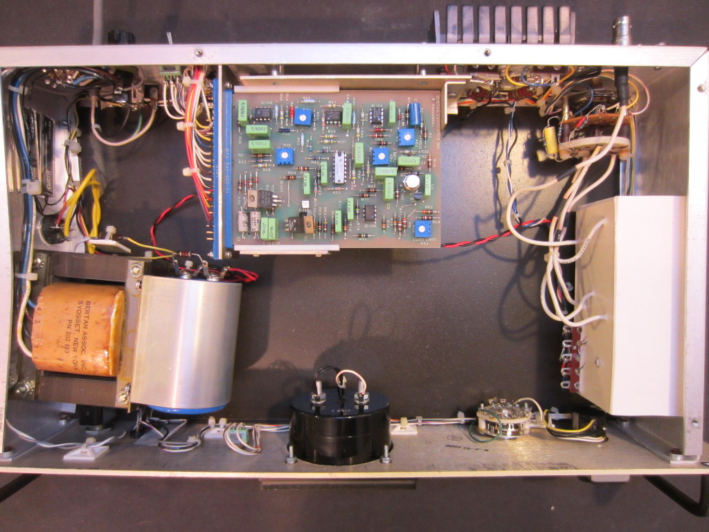
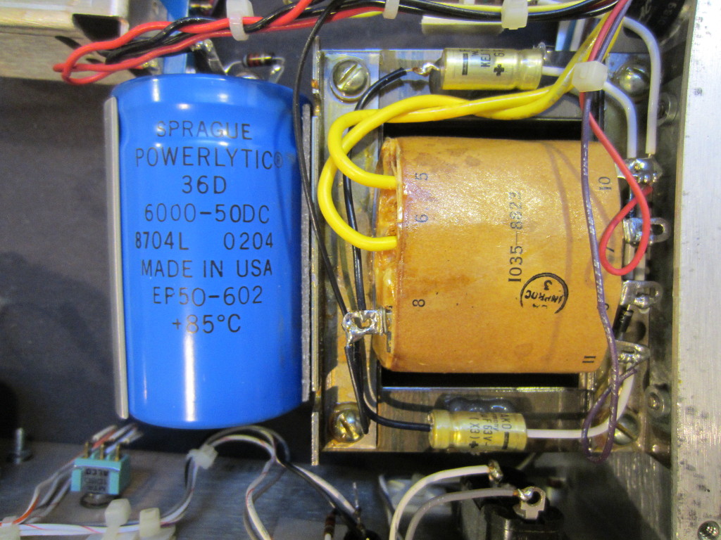
The inside looks surprisingly barren and the build quality looks very crude. Besides the main circuit board, everything else seemed to be using point-to-point construction.
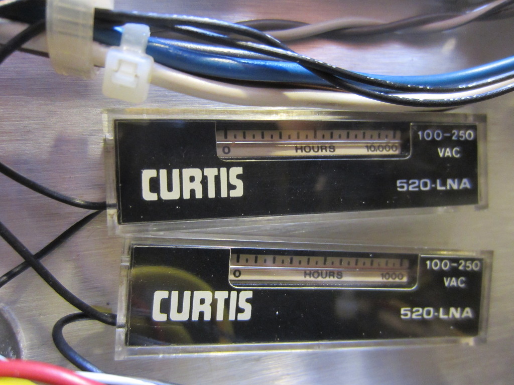
Glued onto the side wall are two Curtis 520-LNA elapsed time indicators (ETIs). This is quite cool as I have not seen this kind of indicators used anywhere else. According to the datasheet, here is how they work:
The integral is achieved by passing current through a precision-bore glass capillary tube. The glass tube is filled with two columns of mercury, which are separated by an electrolyte gap. Application of current causes the mercury at the anode to be electrochemically transferred across the gap to the cathode at a rate which is proportional to the current. Thus the gap moves along the capillary tube and provides a visual indication of the current/time integral.
As you can see, this unit has been in active service for at least 10,000 hours.
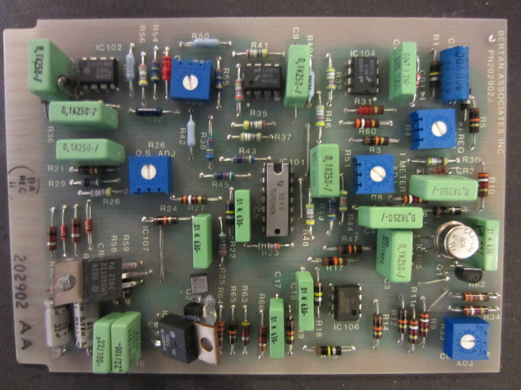
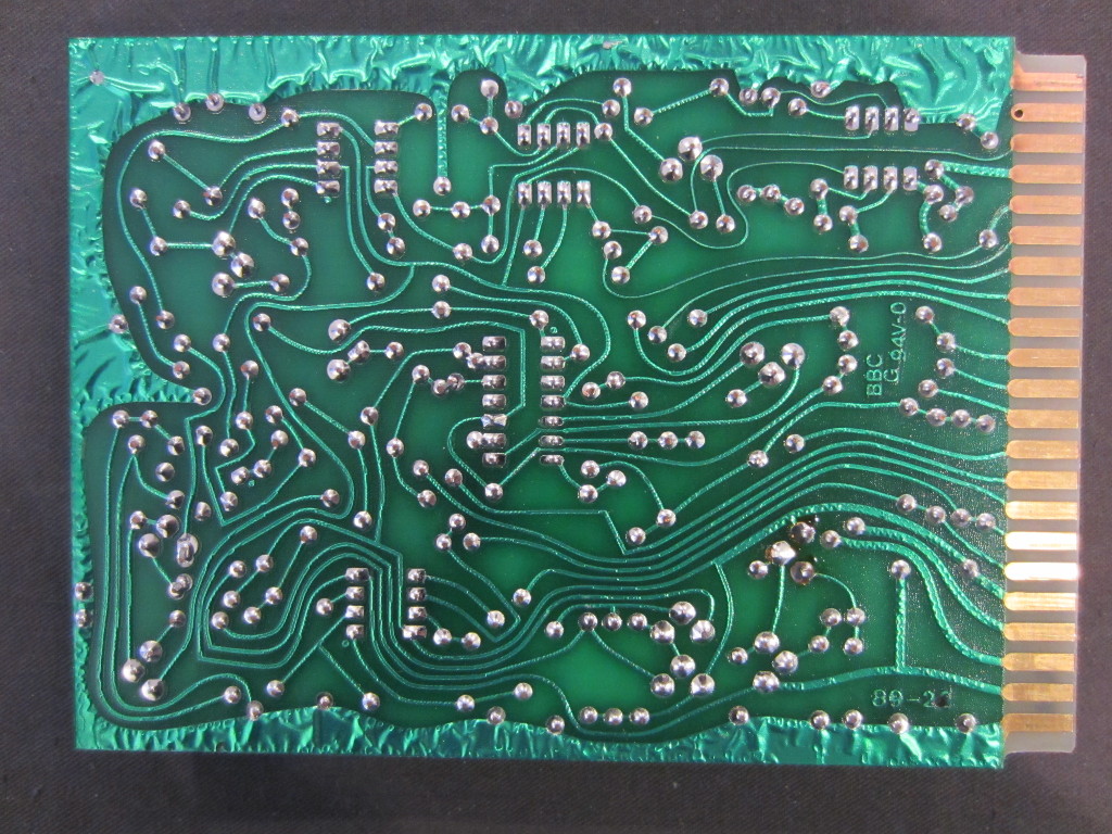
The pictures below shows the top and bottom side of the main board. The main active components here are some Op Amps (LM358, uA1458, TL082, TL083) and transistors. The metal can is a CA3028, which is a high bandwdith differential/cascode amplifier. The onboard oscillator is buffered and then drives the two 2N6578 Darlington transistors that switch the primary of the high voltage transformer inside the potted assembly. Judging from the datecodes, the unit was probably made sometime after 1989.
|
|
To be honest, I have not seen such shoddy construction for a long time. Take a look at the interior of the front panel below, the transistor that drives the LED is glued directly on the case!
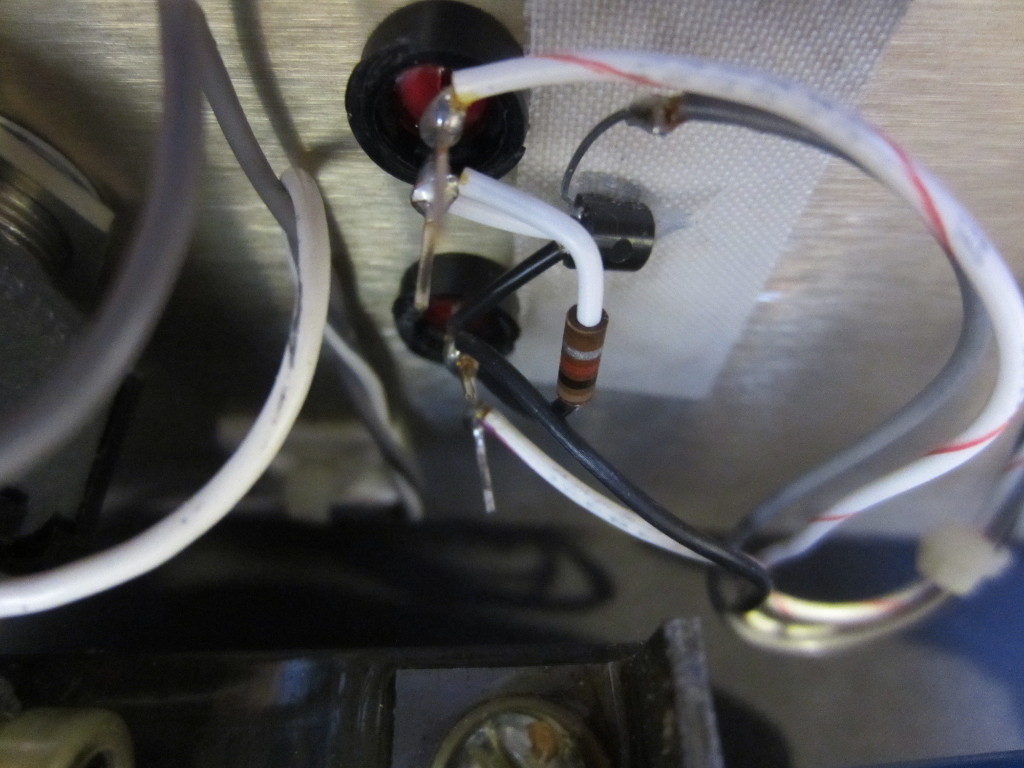
It’s getting even better! Take a look at the auxiliary power rectifier and filter circuit (for the main board), they are glued onto the transformer itself!
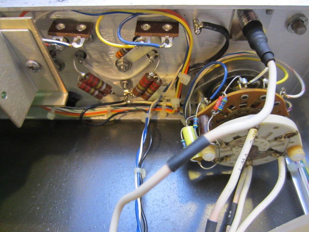
Here is a picture of the output polarity switch and the MHV high voltage BNC output connector. You can also see the load balancing resistors soldered directly onto the pins of the transistors. A few standoff boards can also be seen in the picture.
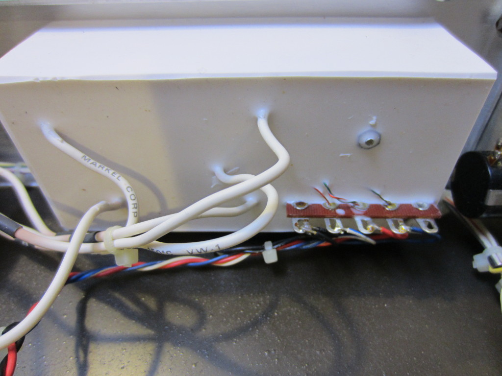
Finally, here is a picture of the potted HV transformer/rectifier assembly.
If you watch the video below, you will see that the reason this power supply is dead is that one of the HV capacitors inside was shorted. Unfortunately, this cannot be easily repaired.

