I bought a Sony A6000 mirrorless digital camera last year to replace my Cannon PowerShot Elph 300 HS point and shoot camera for my YouTube videos. While its fast auto focusing capabilities is great for my teardown and project videos, the A6000 also has some drawbacks. Namely, you cannot shoot video while the camera is hooked to the charger or computer via the USB port. And because of this limitation, continuous shooting could be a challenge as the battery would be depleted rather quickly.
So I bought a battery adapter for it (see picture below, I believe it was a generic Neewer battery adapter) and with a 8.4V power supply I no longer needed to worry about battery life while shooting videos.
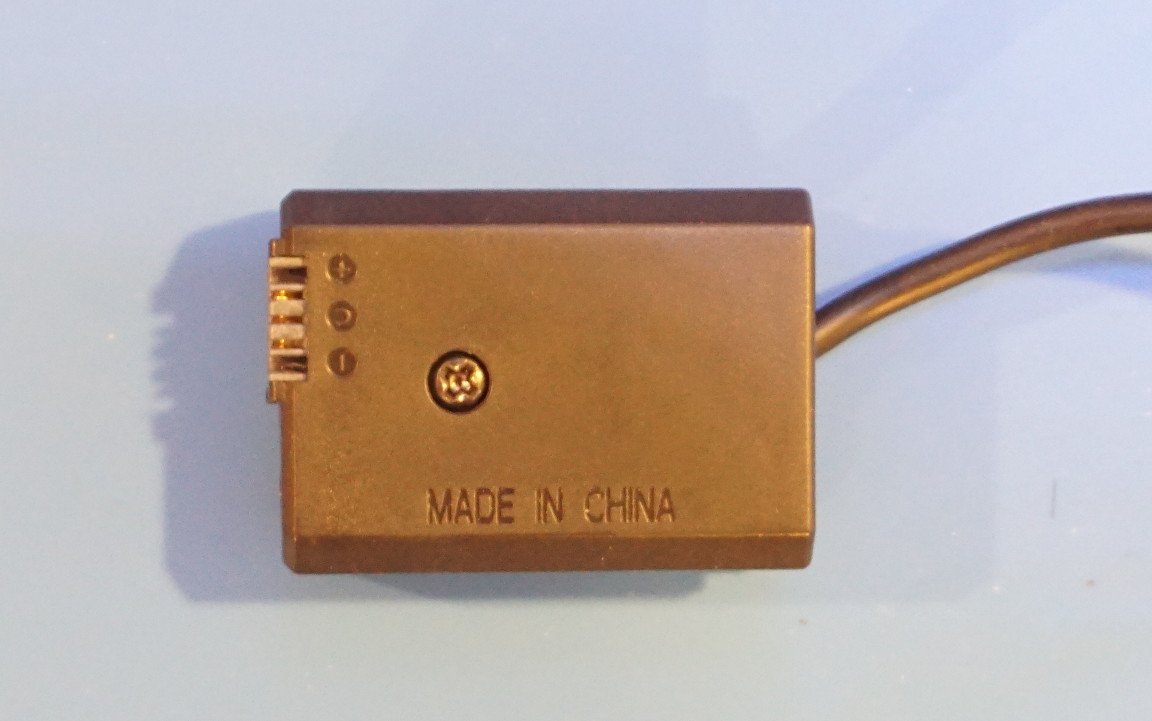
With the battery adapter on hand, I decided to take a look at what’s inside and then use the adapter to measure the power-off/stand-by current of the Sony A6000.
I was not expecting to see much inside this battery adapter. After all, all it needs is the connection between the battery terminals and the input power jack and a resistor between the center pin and the ground in place of the thermistor that is used to sense the temperature of the battery pack. At the most, it might also include a reverse polarity protection diode.
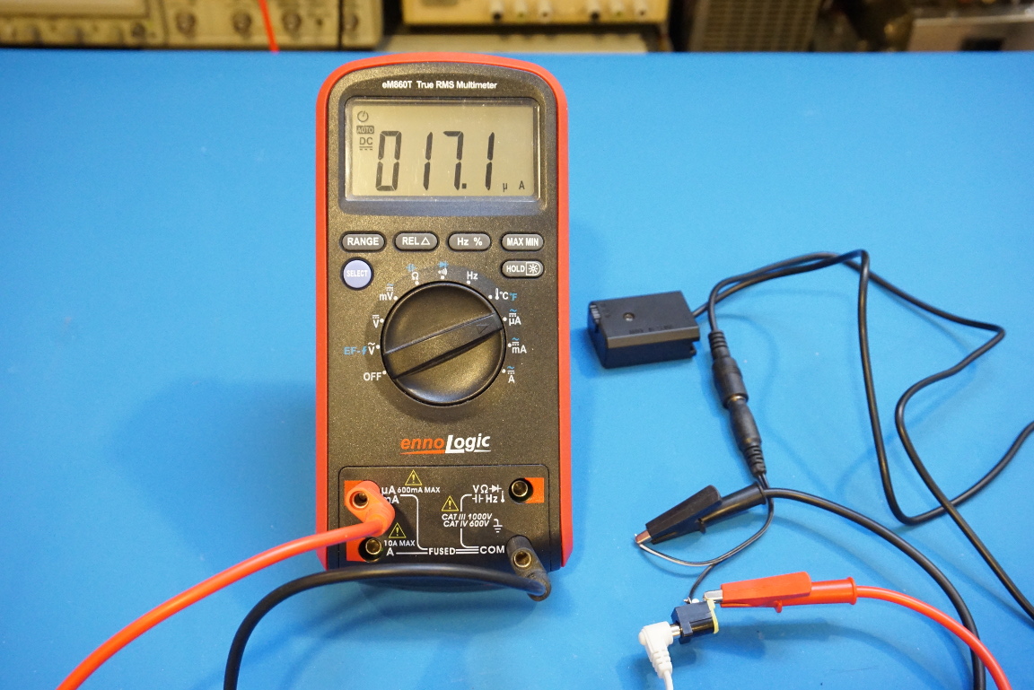
But a quick measurement suggested that there must be some active components inside as the adapter itself draws around 17 µA current when connected to the power source. So clearly, there is some active circuitry inside.
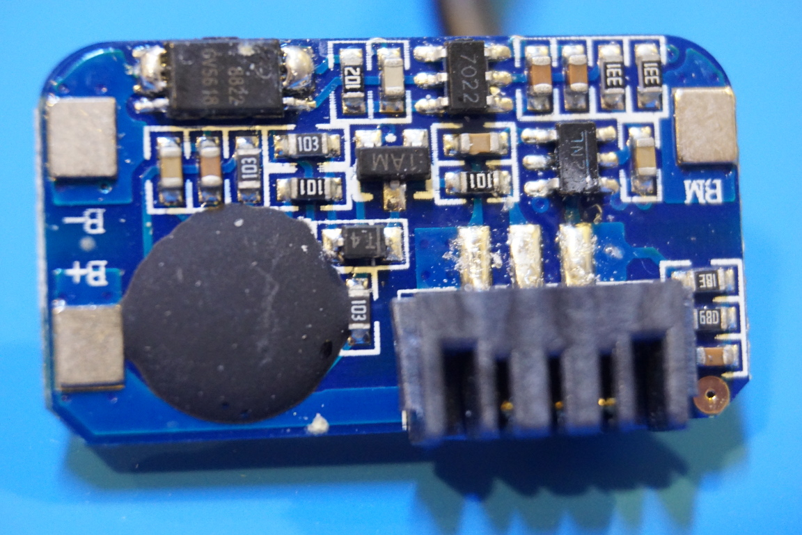
Upon opening up the battery adapter, I was surprised to see the circuit board inside. From the silk screen’s designation it appeared to be a battery management module. Unfortunately, since chip on board (COB) design was used I was not able to find much information on what exactly this board does.
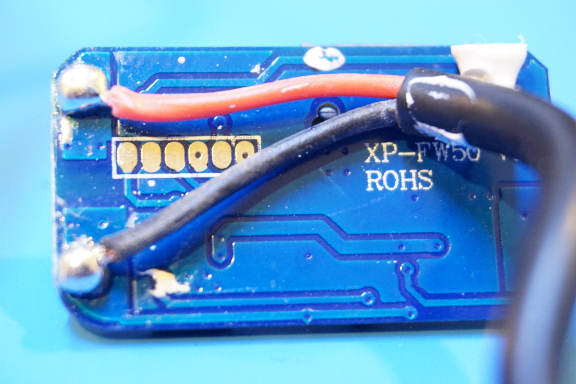
But it appears that the negative power adapter input (B-) is connected to a 4 pin current sensing resistor (Kevin sensing). So presumably the circuitry is capable of measuring the current flowing through the battery terminal. Could this be used for over-current protection? Maybe, but in my experiment I shorted out the battery output terminals and I wasn’t able to trigger the over-current protection for current draw as high as 4A. Since the camera only draws less than 1A, I doubt that it would provide any protection at a current cutoff level any higher than this. So the inclusion of this circuit board inside this battery adapter remains a mystery to me. If you know the purpose of this board, please leave a comment below.
When Sony A6000 was initially released, there were some discussions on the high power-off current draw of this camera and people had complained that a fully charged battery would only last for a couple of weeks if left inside the camera.
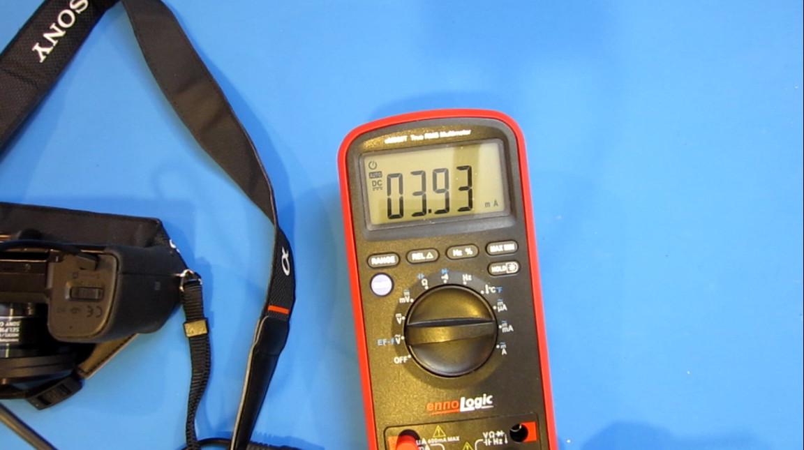
My camera has the latest firmware (version 3.2) and I have noticed similar battery drain issue. With the help of the battery adapter I could easily measure the standby current. And the result was quite astonishing. As you can see in the picture below, the current draw while powered off is close to 4mA! So at this rate it would only take a couple of weeks to fully drain the 1000mAh battery it is equipped with. In this day and age where low power MCUs are abundant, this level of standby current is clearly unacceptable. I suspect however that there is some hardware limitations in Sony A6000’s design as otherwise Sony would’ve already updated the firmware. After all, the A6000 model was released more than three years ago.
Here is a video of the teardown:

