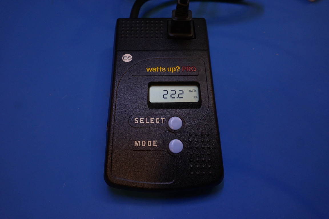
Power meters for measuring power consumption of consumer electronics have been around for at least a decade. The most popular ones are argubly P3 International‘s power meters and many of its clones. I have a later version of the P4400 which was based on a COB design. Some earlier manufactured P4400’s used off-the-shelf ICs. The Watts Up? power meters were first seen roughly around the same time as P3’s Kill A Watt meters. However, they never became as ubiquitous as the Kill A Watt due to their high prices. But compared to Kill A Watt power meters, Watts Up? meters do seem to offer better functionalities. The Pro series for example are equipped with USB interfaces and thus allow easy data logging and data analysis on computers.
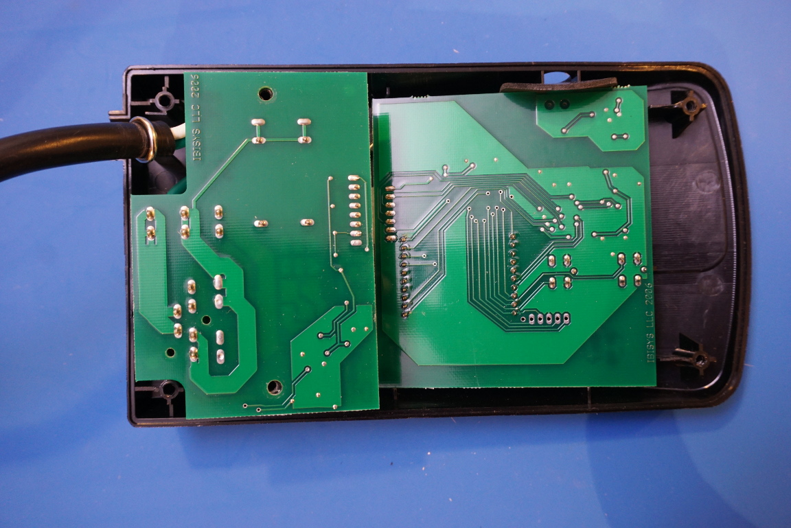
So I decided to open up the Watts Up? Pro ES I have, and see what makes it tick. The meter uses a two board design. The board on the left side as shown in the picture below is connected to the mains and the digital circuitry is housed on a secondary board. These two boards are connected together via a short ribbon cable.
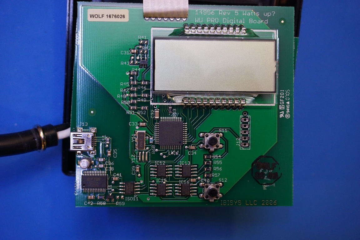
The digital board can be easily accessed. It is based on a Microchip’s PIC18F45J10 microcontroller. This is a rather beefy MCU. It has 32K flash memory and 13 10 bit A/D channels. UART, SPI and I2C are all supported in hardware. Judging from the location and the pin connections of the MCU, I think it is primarily used to drive the user interface (e.g. the tactile switches and LCD). So clearly, the power measuring task is handled elsewhere.
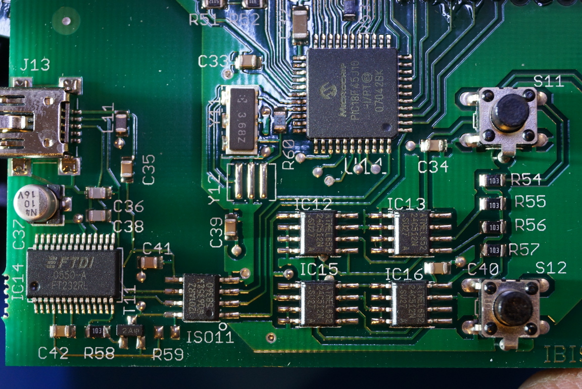
Here is a close up picture of the digital board. As you can see, four 64K 24C512N EEPROMs are used for information logging. Depending on the frequency and number of data points chosen, the Watts Up? Pro ES is capable of logging continuously with hours to days worth of data points.
Since Watts Up? Pro allows communication with a PC via USB while it is plugged in, it utilizes an ADuM1201 dual channel digital isolator IC from Analog Devices for galvanic isolation of the Rx and Tx serial lines. Without this isolation, you could easily destroy the connected device and/or the power meter itself while doing measurements. For instance, if you try to measure the PC’s power consumption while logging to the same PC via the USB connection. The serial to USB conversion is handled via the venerable FT232RL.
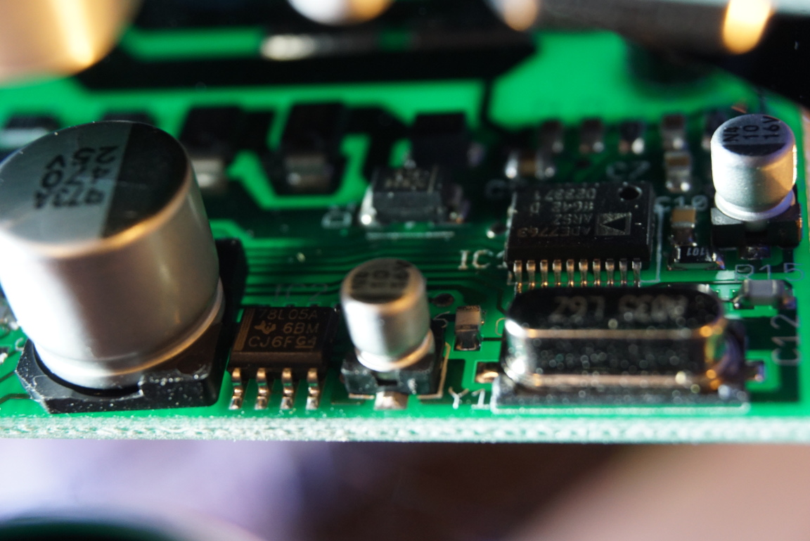
The power measurement is done via a dedicated power metering chip ADE7763 located on a secondary PCB which house the mains connection. ADE7763 is a single-phase active and apparent energy metering IC, which handles all the essential measurements. It is controlled by the PIC18F45J10 via the 4-wire SPI protocol. In the picture below you can also see a 78L05A 5V regulator chip. Interestingly, the PIC18F45J10 operates under 3.3V only and by measuring the voltages supplied to the digital board I could confirm the presence of the 3.3V voltage. So it is possible that the 5V regulated voltage is further stepped down via a discrete regulator circuitry on the board somewhere. Because the board is soldered onto the pins of the PCB mounted IEC receptacle, I was not able to remove the board for further investigation.
For those who are interested, here is a video of this teardown. You can also see some measurements done using this power meter.

