IRIG time code generators (not to be confused with the ones used in video and film industry) are often used for clock synchronization among various connected equipment and is commonly used in power generation and distribution industry as well as in the military. In this blog post we will take a look inside a Datum 9300 time code generator from the late 80’s. A video detailing the teardown is linked towards the end of the post.
The IRIG (Inter-Range Instrumentation Group) time code standard was developed back in the 1960’s. The standard itself defines a family of rate-scaled serial time codes which captures the date time information. The codes themselves can be binary coded decimal (BCD) or straight binary seconds (SBS) and is commonly amplitude-modulated onto a carrier frequency. The Datum 9300 time code generator for example, has outputs of both 1kHz (IRIG-B) and 10kHz (IRIG-A) carrier frequencies.

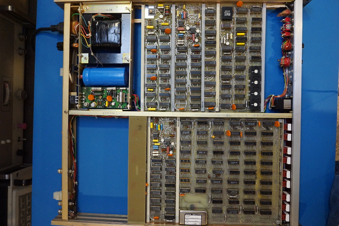
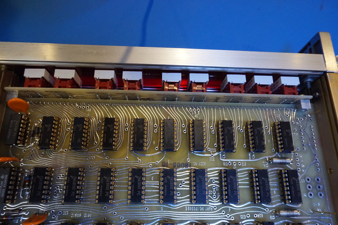
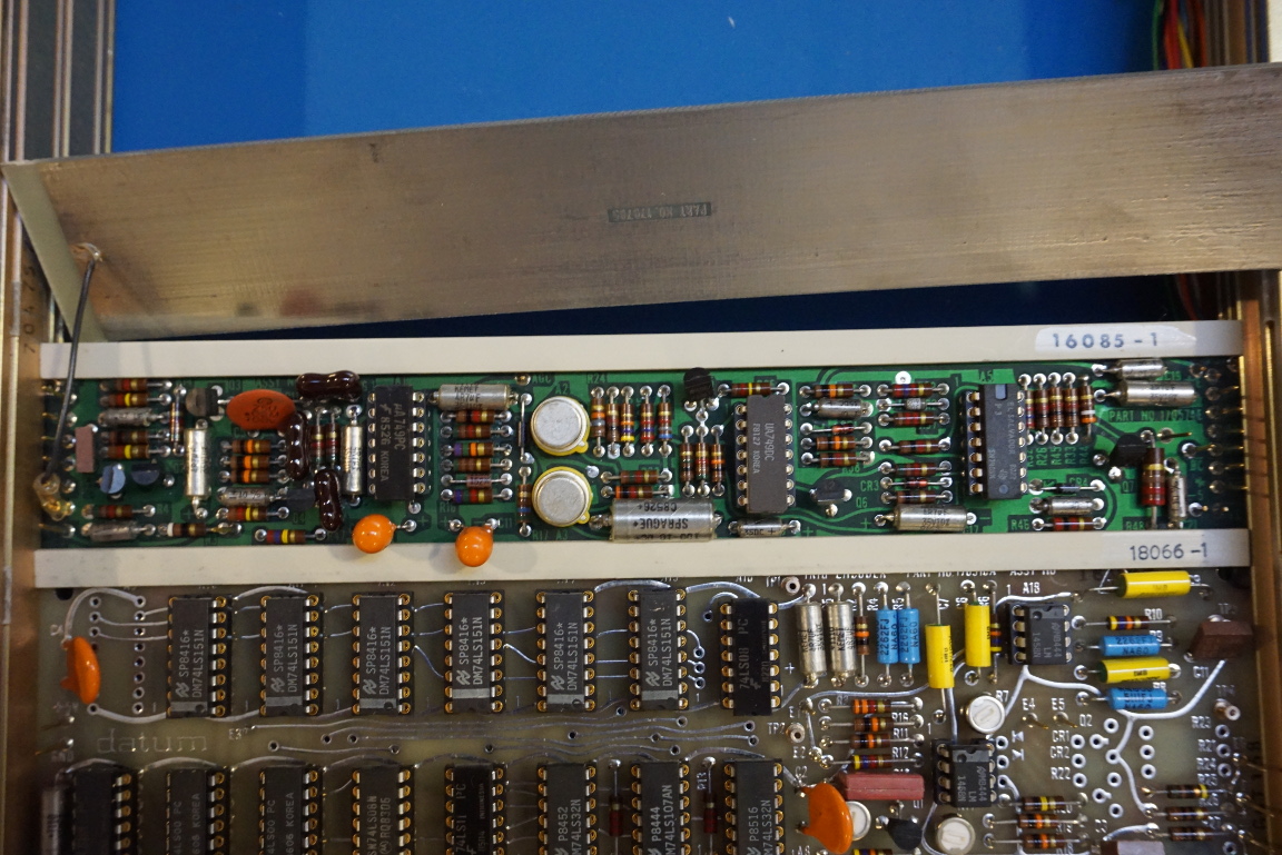
Upon opening the covers, we can immediately see the old school construction inside. Most of the ICs are 74 series TTL ICs. We can see the use of logical gates (74LS32, 74LS86, 74LS10…), flip-flops (74LS76, 74LS73, 74LS103…), counters (74LS193, 74LS192…) and decoders (74LS156, 74LS42, DM9374…) just to name a few. We can also find a few OpAmps presumably used for carrier frequency generation and modulation.
Every single one of the ICs inside this unit is socketed, making chip replacement a breeze.
|
|
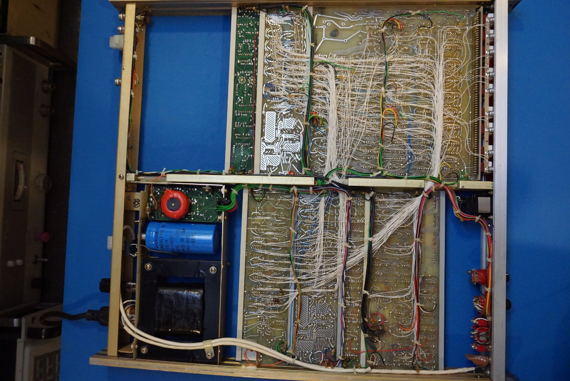
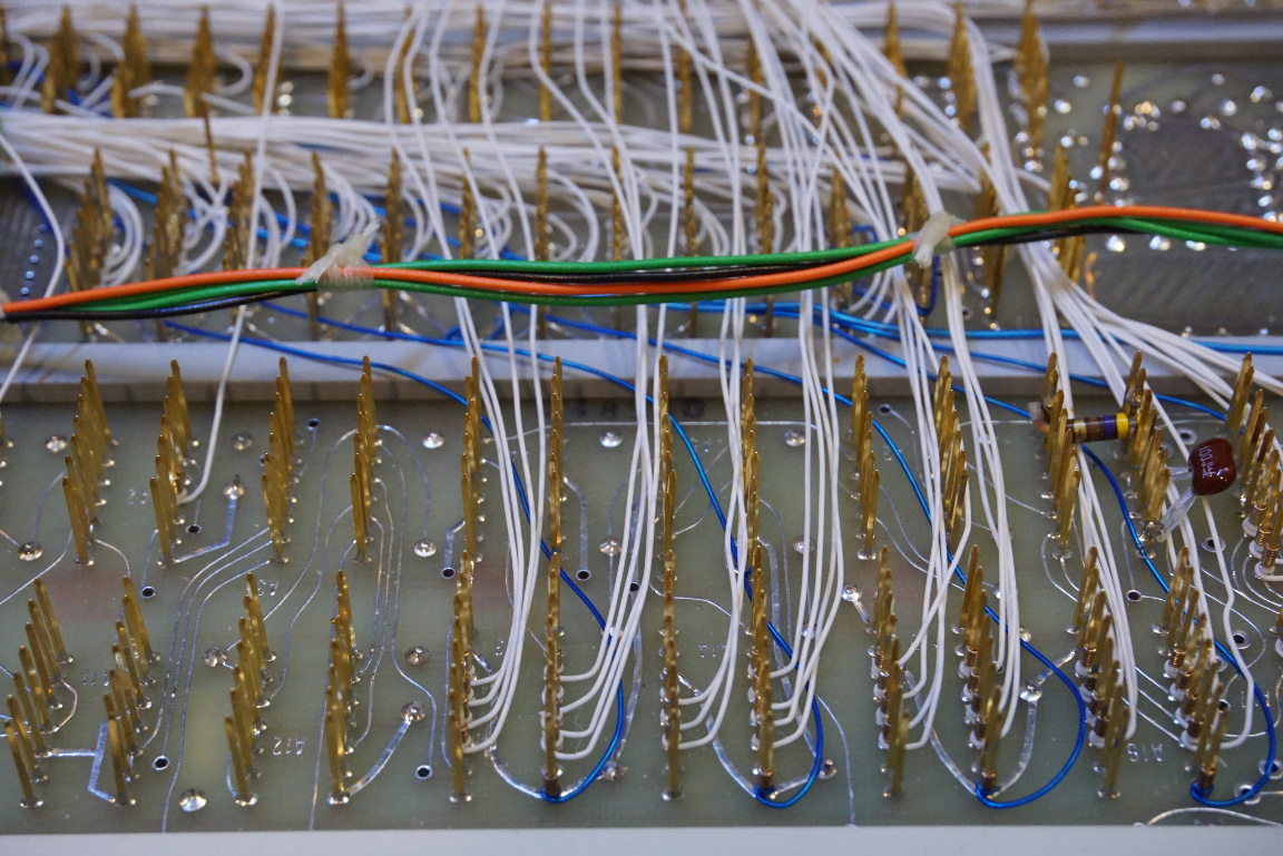
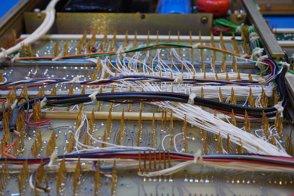
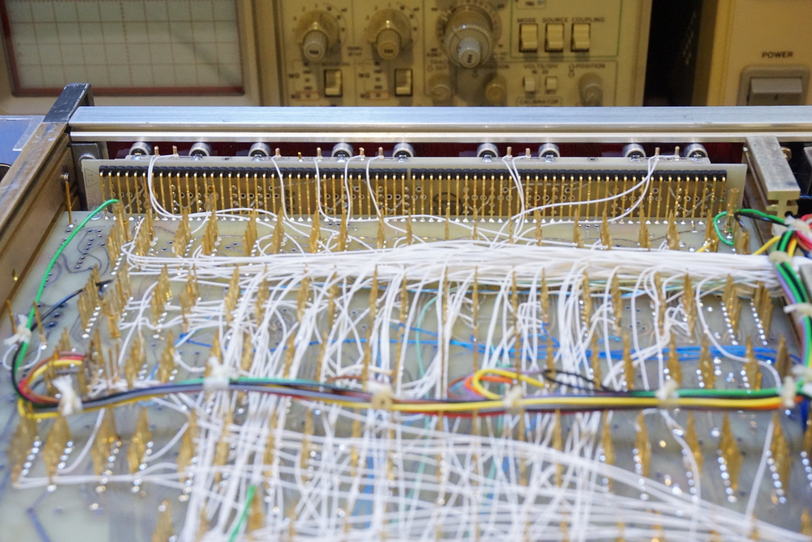
The bottom side of the PCB looks stunning. Because of the IC densities on the PCB wire-wrapping techniques were used to make the various interconnects. Although the PCBs used here are double sided, it is apparently insufficient to route all the required connections within the PCB itself. The following are a couple of closeups of the wire wrap construction on the bottom side of the PCB. All the wiring is arranged meticulously.
Although wire wrapping has long become a thing of the past, these DIP sockets used for wire wrapping remain readily available among most suppliers.
|
|
Even the front panel 7-segment displays are socketed. A separate PCB for the display is then connected with the mainboard using right angle rigid interconnects. The level of attention to detail is quite astounding. Clearly, cost was the last thing went into consideration when this unit was first manufactured.
|
|
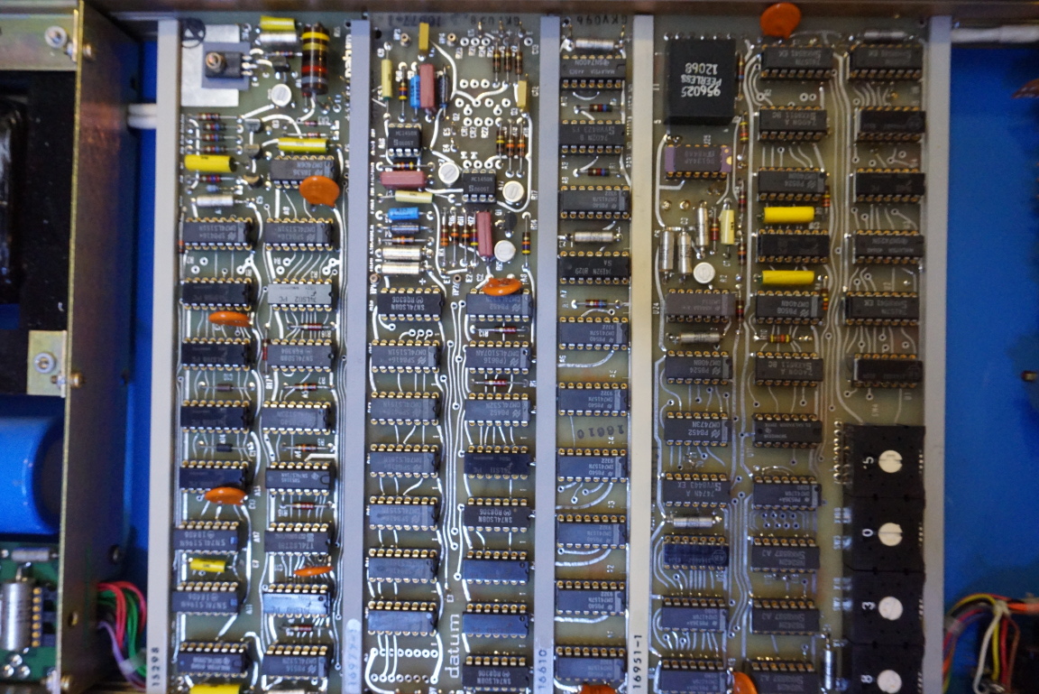
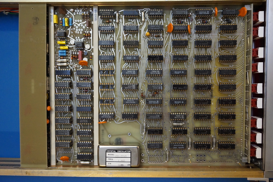
Here again are a couple of closeup pictures of the boards. In the picture to the right below, you can see the main oscillator used in this Datum 9300. Interestingly, it is just a plain crystal oscillator (or at most a temperature compensated one) and not a more stable source such as an ovenized oscillator. Of course, the job of a time code generator is to synchronize clocks among different devices to the same master clock and the actual accuracy is not all that important.
Modern time code generators often incorporate a GPS disciplined oscillator or a Rubidium oscillator to achieve better accuracy.
|
|
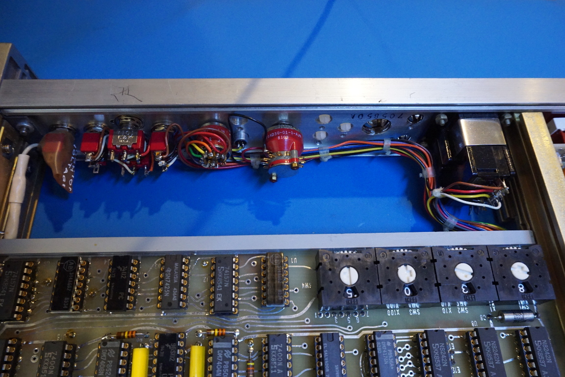
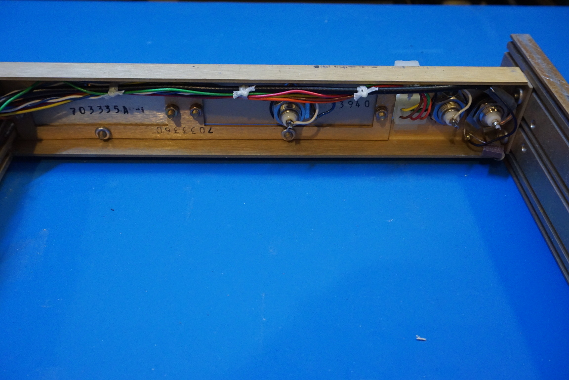
In the picture to the left below, you can see the rotary switches used in the system. The way you set a specific number at a particular digit in this Datum 9300 is to use the number dial to dial in the number you want and then press the momentary button located underneath of the number display you wanted to set the number to.
And in the picture to the right, you can see that a portion of the circuit was shielded using a piece of single-sided PCB. This section of the circuit is for modulating the output signal perhaps?
|
|
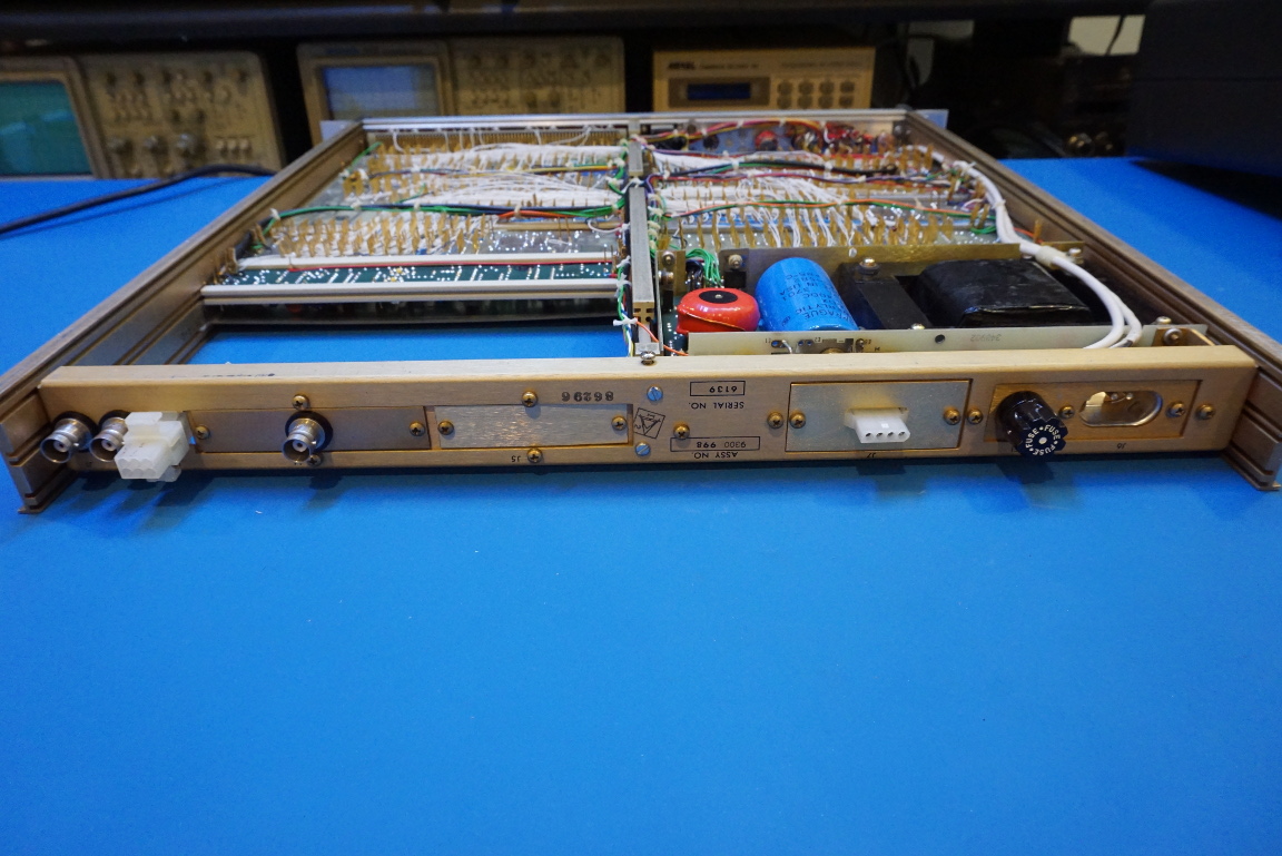
Here are a couple of pictures showing the back side of the unit. Two of the BNC outputs are for the 1 kHz and 10 kHz time code signals and the third one sends a synchronization pulse when the “start” button is triggered from the front panel.
The serial number printed on the chassis reads 6139. If that number suggests the number of units made so far, it is actually quite sizable.
|
|
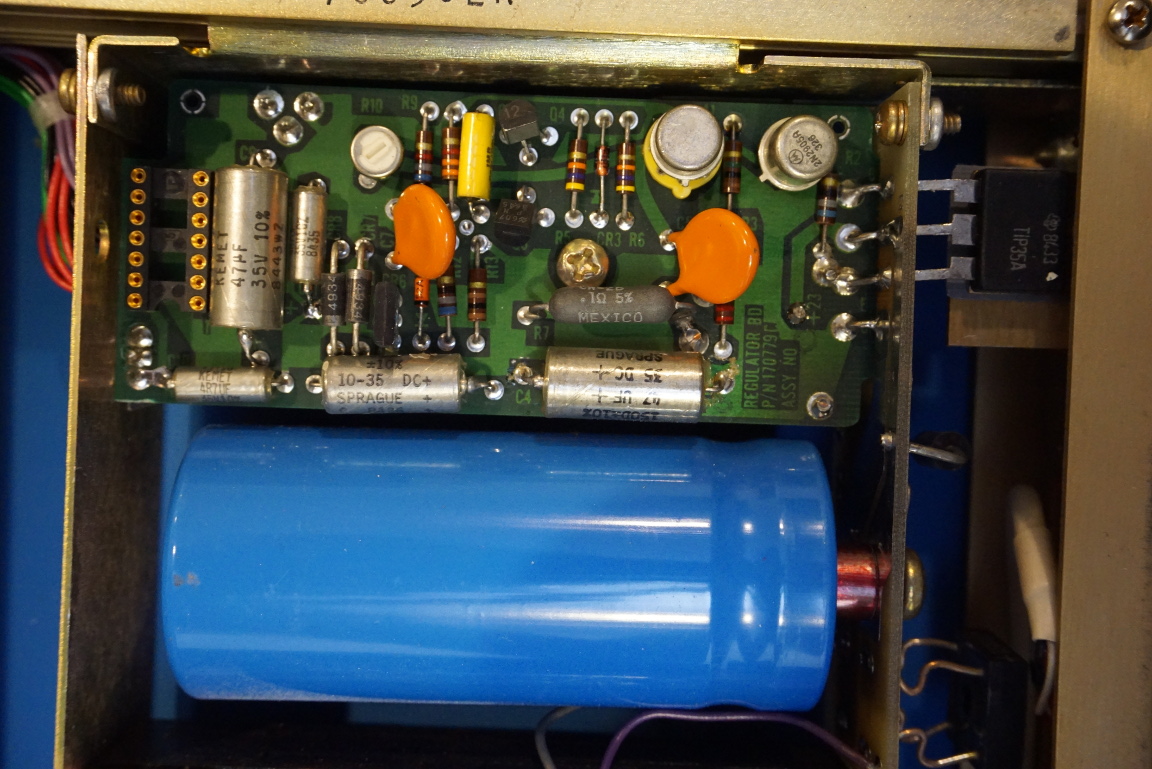
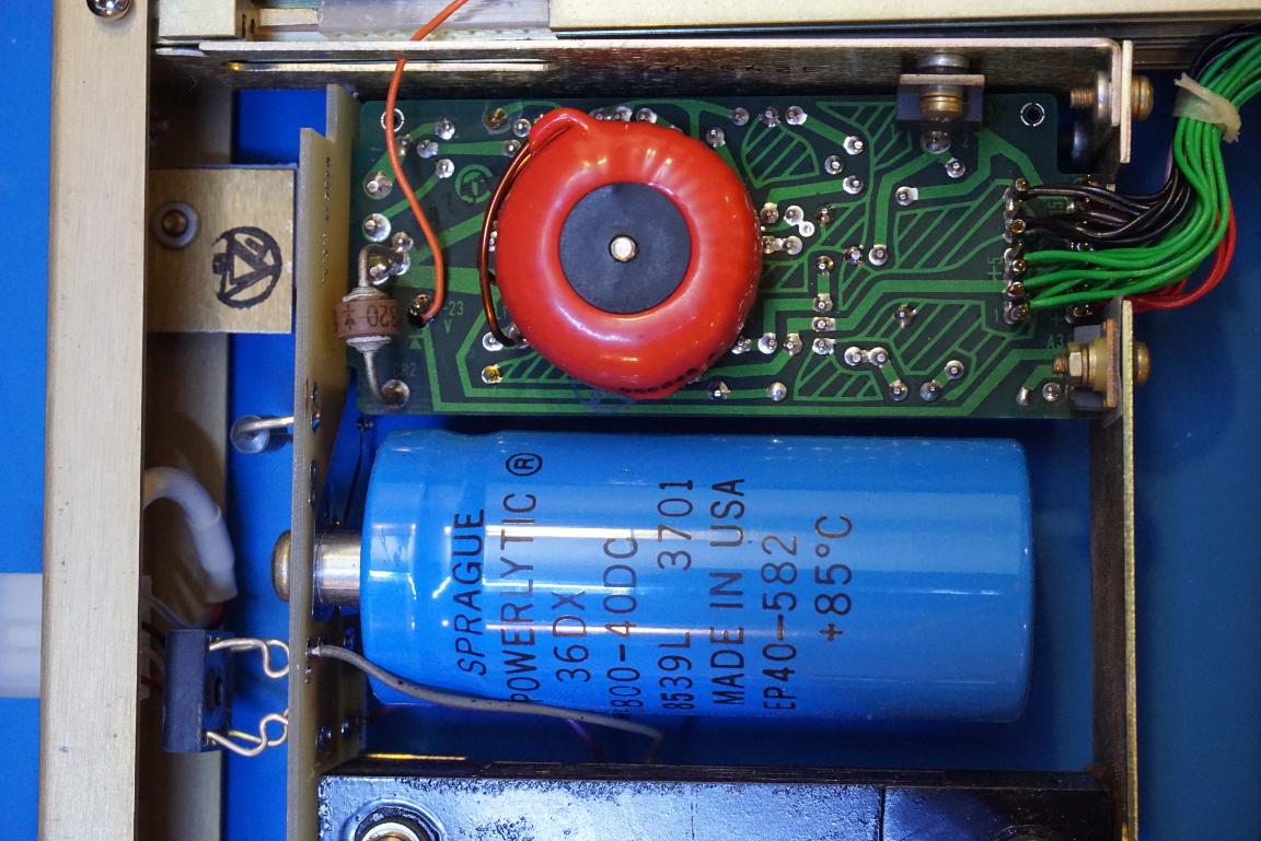
The power supply inside the Datum 9300 is actually a switched mode DC-DC converter. This is a little surprising I guess since most of the equipment back in the 80’s were using linear regulators.
This DC-DC converter converts the 24V input voltage into 5V for the TTL chips and ±15V for the OpAmps.
|
|
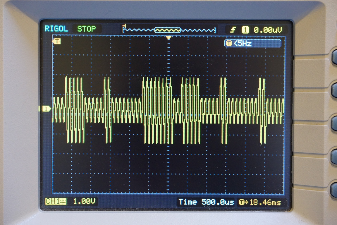
From the oscilloscope capture below, you can see the waveform of the IRIG time code generated from the Datum 9300.
And finally, here is a video of the teardown for those who are interested.

