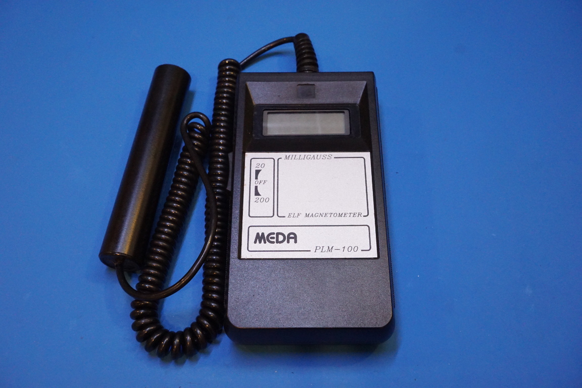
I did a teardown a while ago on a cheap eBay electromagnetic radiation detector, and if you recall the performance of that meter was mediocre at the best. This time around though, I’ve got a MEDA PLM-100 AC magnetometer. Since MEDA (Macintyre Electronic Design Associates) specializes in fluxgate and search coil magnetometers, this PLM-100 magnetometer is a piece of professional test equipment. In this blog post, you will see some teardown pictures and for those who want to see some real world actions you can take a look at the video included towards the end.
Although I could not find much information about this particular magnetometer, from MEDA 8532‘s datasheet there was some reference to the PLM-100 and it states that:
The PLM-100 series unique sensor signal conditioning minimizes errors caused by sensor movement within the earth’s magnetic field. This quality instrument provides a reading accuracy of ±1% traceable to NIST and precision to 0.01 milligauss.
So as you can see the performance of this meter in terms of both accuracy and sensitivity is quite impressive. AC magnetometers like this one are commonly used in EMC (Electromagnetic compatibility) testing.
From the picture below, you can see the output wires from the sensor soldered onto the PCB. Since there are only two wires, it is pretty indicative that the sensor used is a calibrated search coil sensor. For an AC magnetometer, the induced current signal picked up via the search coil is typically amplified by a transimpedance amplifier to produce a measurable output voltage. Transimpedance amplifiers are also widely used in low level current measurements as feedback ammeters (I made one many years ago and it was quite useful due to its extremely low burden voltage).
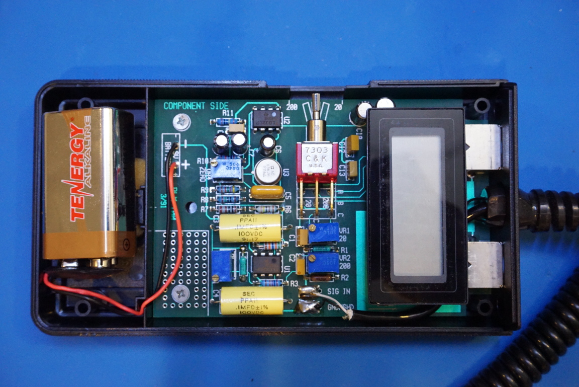
Given the sensor size, this magnetometer was probably designed mainly for power line harmonics field measurements. The op-amp used are two TL032 JFET-input low offset general purpose ones. Judging from the traces, the TL032 towards the top in the picture below forms the transimpedance amplifier. The amplified voltage signal then goes through an AD636 true RMS to DC converter so the final voltage signal can be fed into a 3½ display.
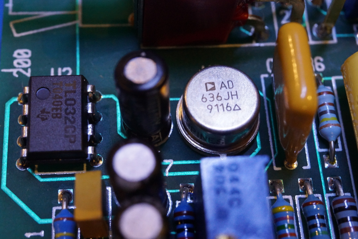
Below is a closeup of the AD636 and its surrounding circuitry. The “9116” date code suggests that this unit was made some time in the early 1990’s. Because this magnetometer has two additional outputs (RMS and wide-band), the second TL032 on the circuit board is probably used for bandpass filtering.
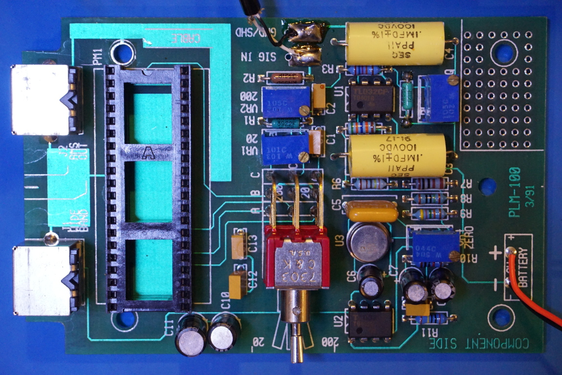
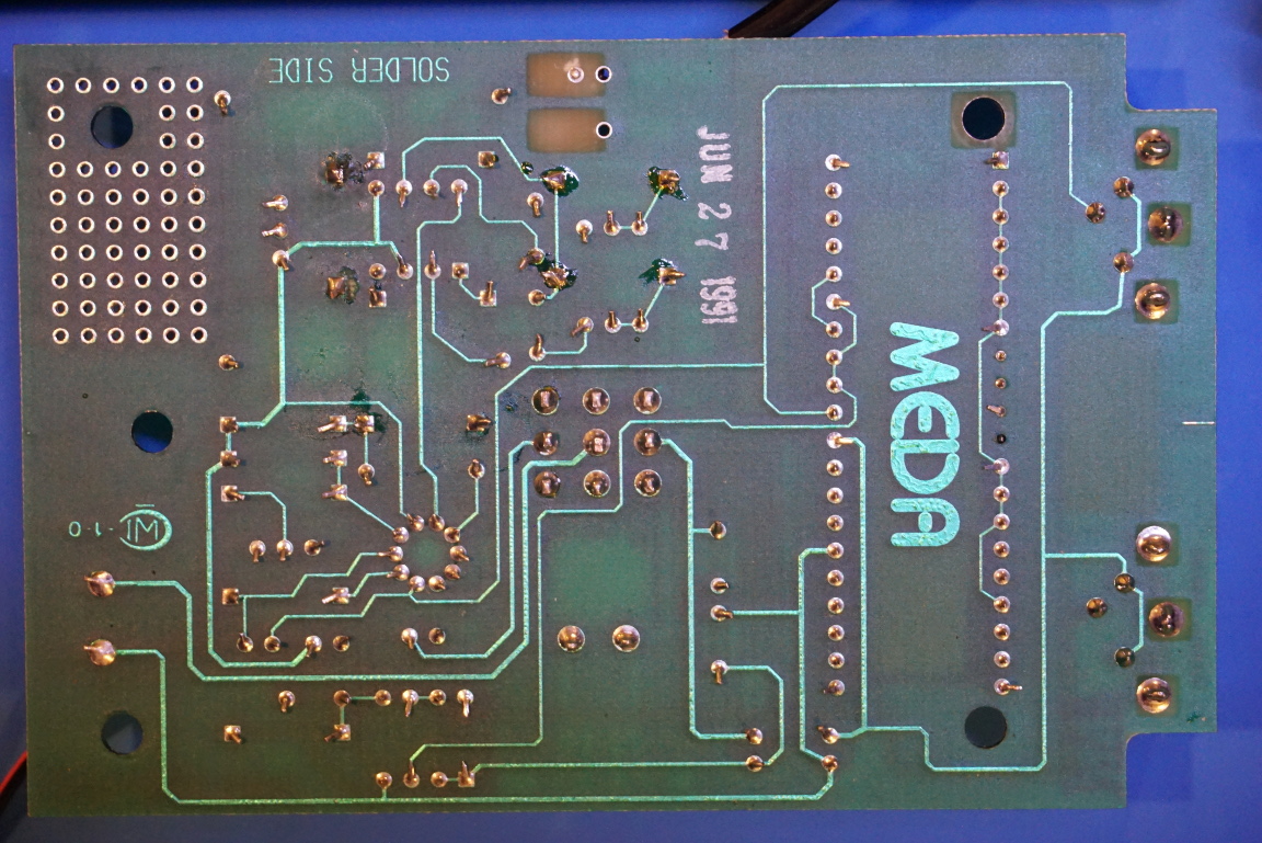
Here is a picture showing the reverse side of the board. It is pretty interesting that the board has a decorative prototyping area.
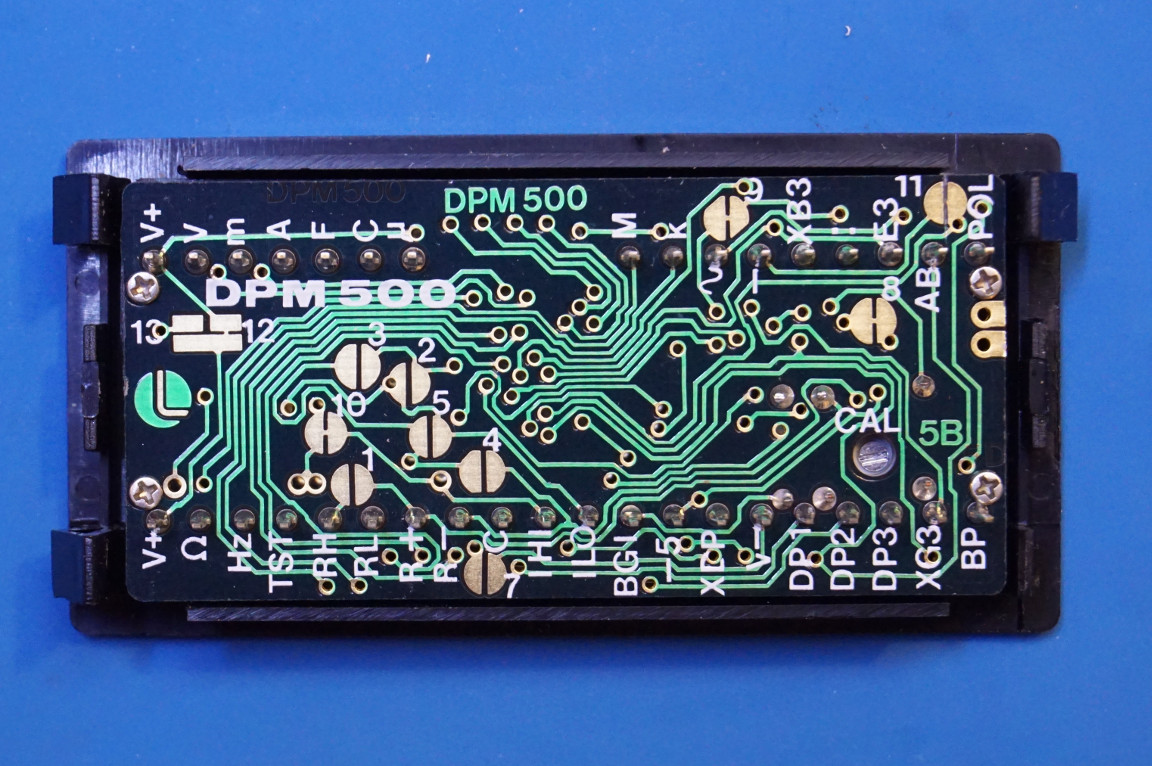
Since there is no dedicated display circuitry on board, an off-the-shelf 3½ display is used. From this picture, it appears that the display used is a DPM 500 from LASCAR Electronics. This display module is still in production and does not sell cheap. It comes at a price of more than $50 per unit with volume purchase. And from the pictures on LASCAR’s website it does not appear that much has changed in the PCB layout design in the last thirty years.
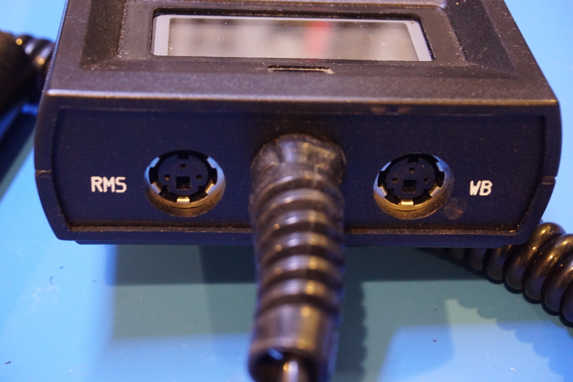
Here is a picture showing the DIN connectors for the RMS and wide band outputs.
And finally, here is a video of this teardown along with some real world measurements.

