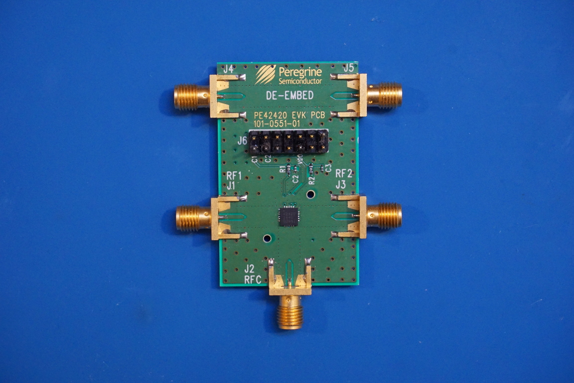
I recently bought a few Peregrine Semiconductor‘s PE42420 RF Switch evaluation boards on eBay. The PE42420 is an absorptive SPDT RF switch that operates between 100 MHz and 6 GHz. Besides the obvious use as a single pole double throw RF switch, we will take a look at using it as an RF modulator due to its fast switching time (~300 ns) in this post. A video of the experiments discussed in this post can be found towards the end.
As an RF switch, the PE42420 provides high linearity and isolation with less than 2 dB of insertion loss across the operational frequency range. And the switch can be controlled easily via two voltage inputs.
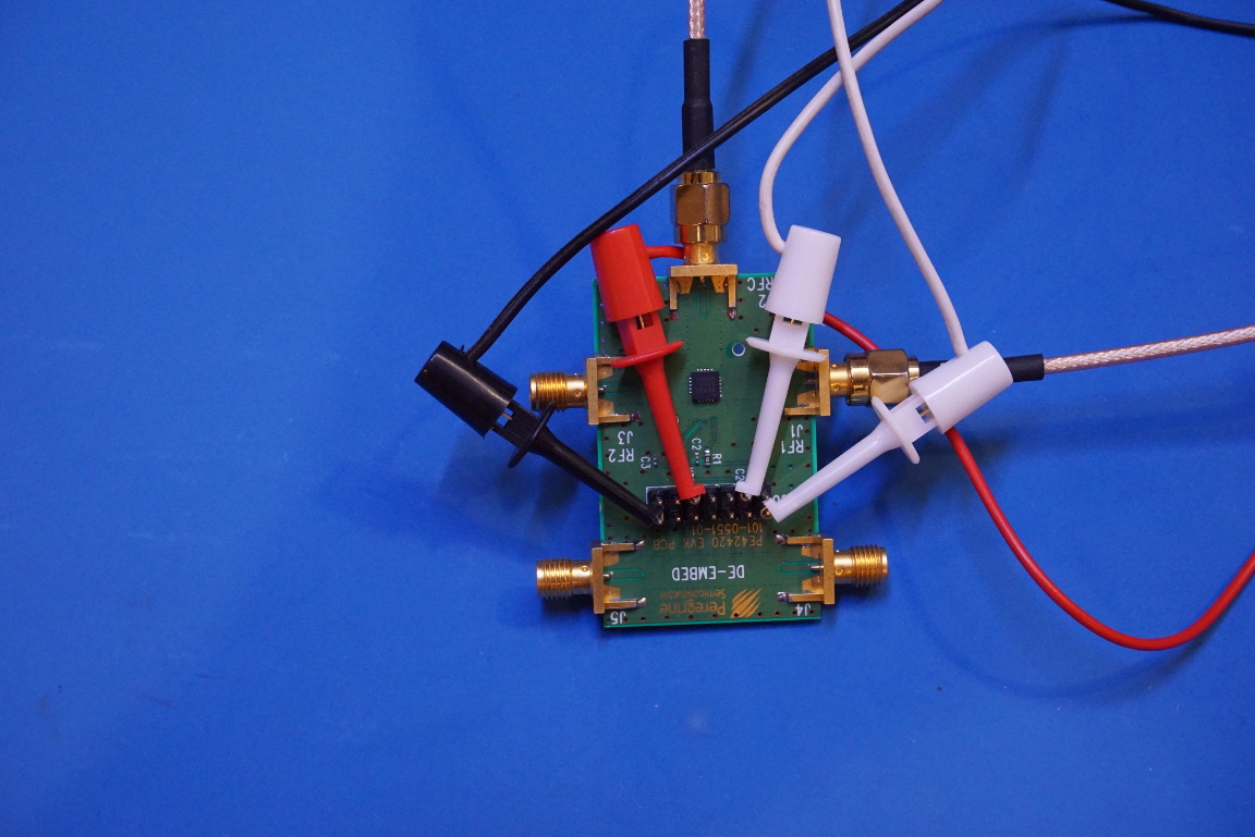
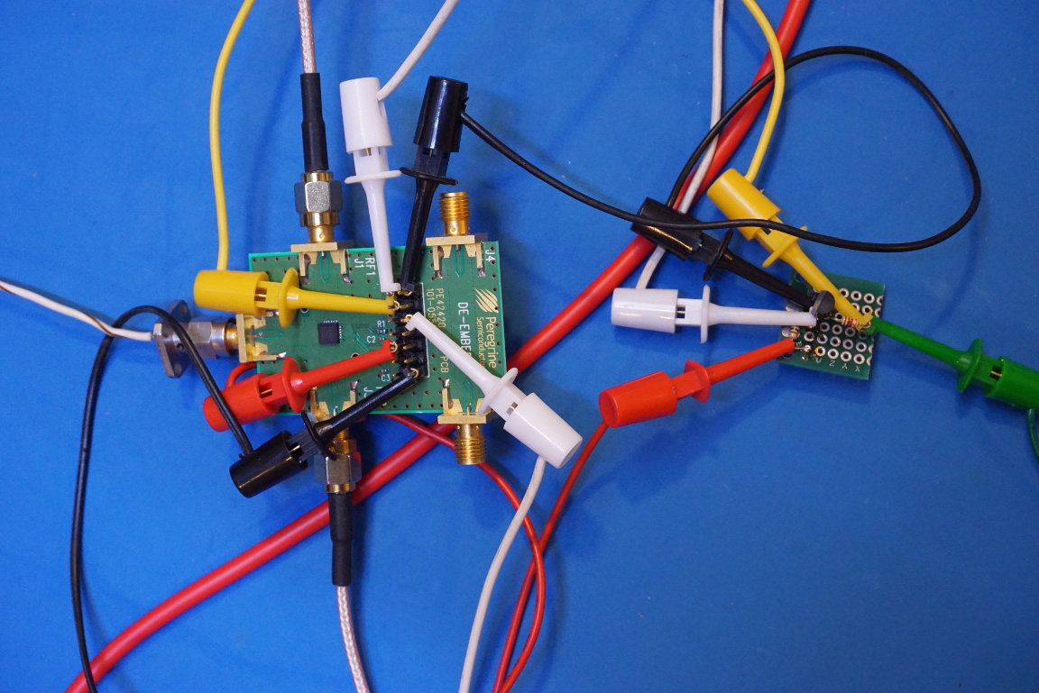
It is equally convienent to use it as an OOK (on-off keying) modulator with an RF signal source. In the experiment below, a 2 GHz RF signal from an HP 8671A is inputted into the RF1 jack, and a 0V – 2V squarewave from a Wavetek 395 is applied to one of the control pins of the PE42420, and thus chopping the output RF signal. By definition, this setup forms an OOK modulator.
Unlike in typical OOK scheme where the RF power is switched on and off depending on modulation, the RF input power remains constant. It is merely absorbed by the on-chip 50 Ω termination resistor during the off cycle. So the efficiency of this modulation method is low. But it is a very convenient way for achieving OOK since not all RF sources can be turned on and off rapidly enough for modulation purposes.
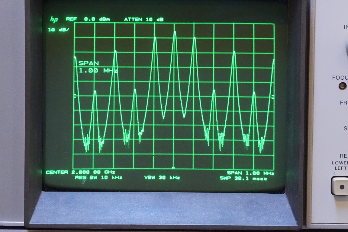
The picture below shows a 1 kHz OOK modulated signal with a 2 GHz carrier frequency. The frequency span in this and the subsequent pictures are set to 1 MHz.
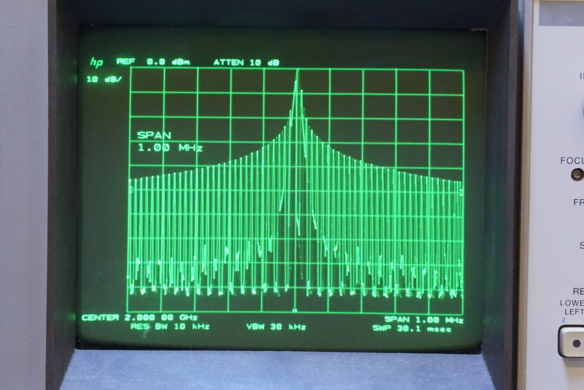
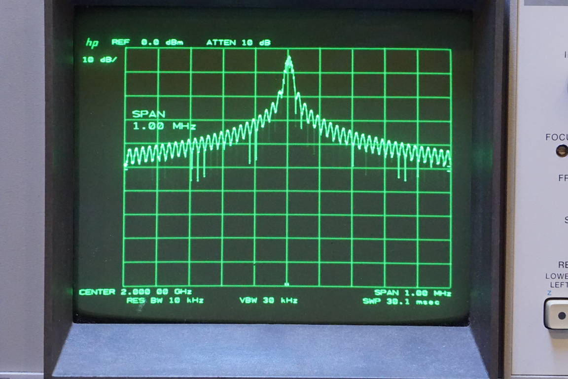
In the picture to the left below, the modulation frequency was increased to 10 kHz. You can see the broadening of the occupied bandwidth due to the increased modulation frequency. In the picture to the right below, the modulation frequency was again increased to 100 kHz. The spectrum spreads further as a result.
|
|
Frequency-shift keying (FSK) can also be accomplished by supplying two different frequencies to RF1 and RF2 ports. And by switching between these two ports the signal output from the center port becomes an FSK signal.
In the experiment setup below, the modulation signal from the Wavetek 395 is inverted using a simple transistor inverter (on the right) so the frequency content of the output can be switched between the two inputs by alternating the control signals.
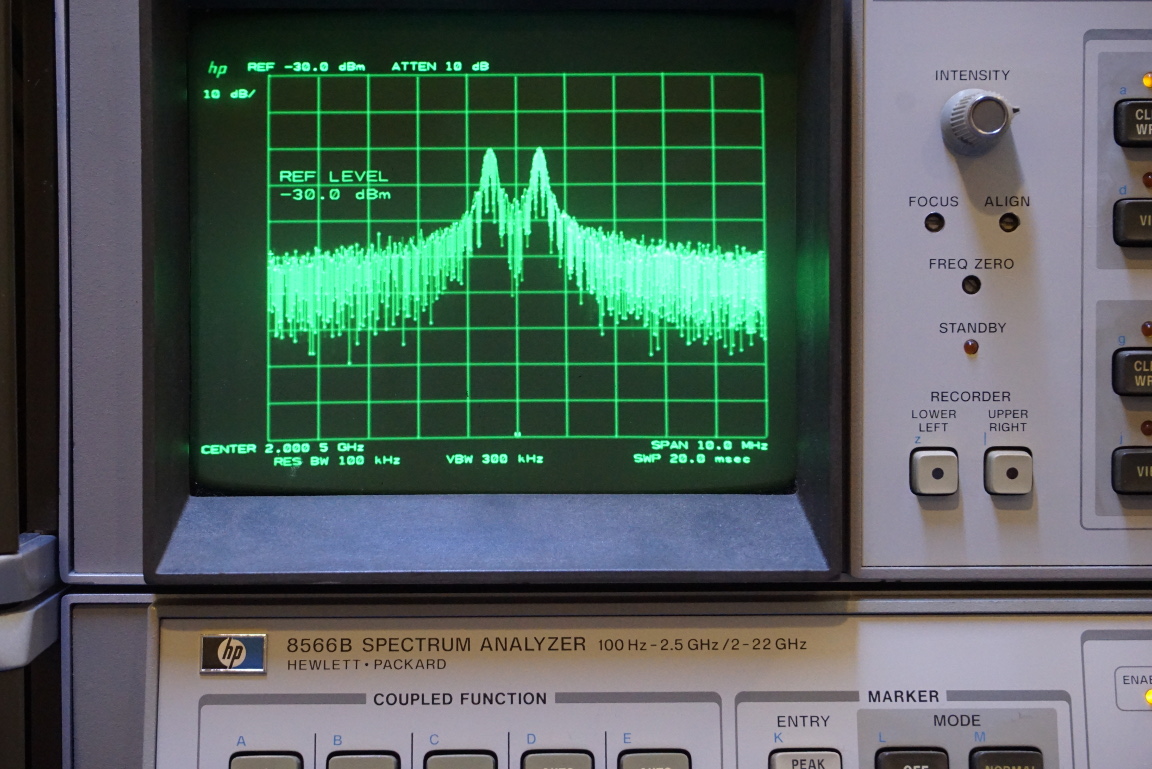
For the experiment, a 2 GHz signal is taken from an HP 8671A RF synthesizer and a 2.001 GHz signal is taken from an HP 8642B, the two signals are 1 MHz apart.
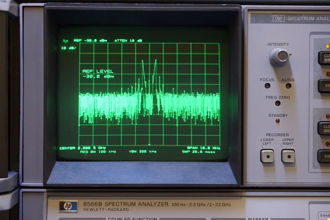
The picture below shows the FSK spectrum (centered at 2000.5 MHz with a frequency span of 10 MHz) when modulated by an 1 kHz square wave. Note that because the two RF signals and the modulation signals are not correlated, the switching between the two signals happen at an arbitrary phase and this manifest as the increased phase noise in the spectrum.
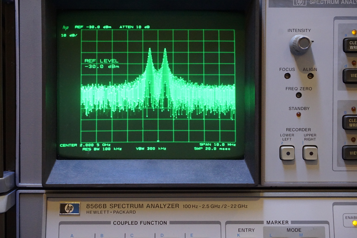
And these two pictures show the FSK spectrum when modulated by a 10 kHz and 100 kHz square wave signal respectively. Again, notice the spread of the occupied bandwidth as the modulation frequency increases.
|
|
Here is a video of the experiments:

