Have you ever wondered what is inside of a 15 year old commercial color projector? Well we will find out in this post today. As usual, a video of this teardown is included towards the end of the post.
At my work place, old electronics are routinely being thrown out. My understanding is that the company actually pays to have these “junk” hauled away and recycled. Over the years I had rescued many perfectly working equipment from their premature death sentences. Some were thrown out because they were old and obsolete. Some were broken due to harsh treatment at work. And occasionally, I would find an item interesting and take it home for further investigation. This time, a Panasonic PT-L780U 3LCD Projector was to be junked so I asked whether I could take it home.
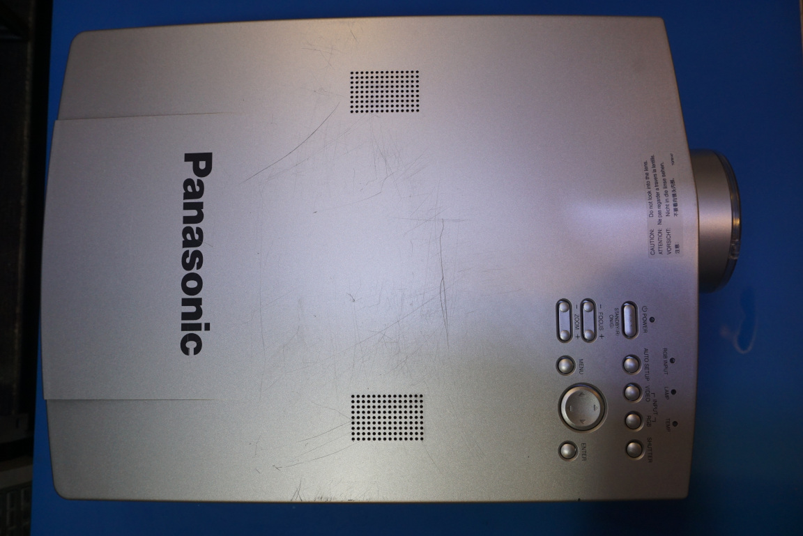
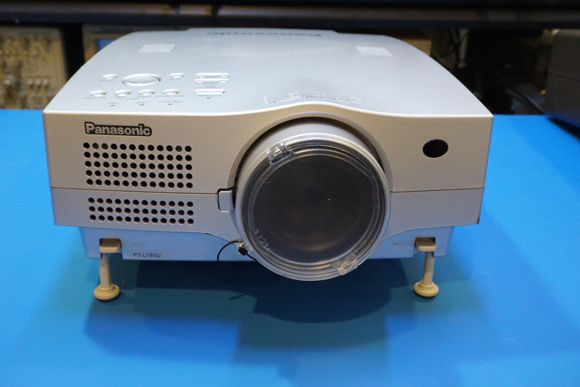
This projector debuted back in late 2003 according to the press release I found online. So by the standard of any modern electronics it is considered to be ancient, at least several generations behind in terms of technology. It is bulky (11-7/17″ W x 5-3/8″ H x 16″ D), heavy (12.8 pounds) and loud, but surprisingly still in working order.
When it was first announced back in the days, it cost a whooping $6,199! Like many electronics, decades later though you can find one in working order on eBay for a hundredth of the original cost.
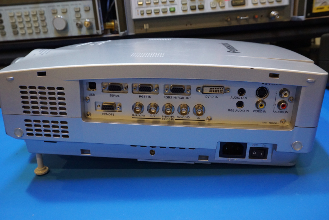
Of course, the PT-L780U is a commercial projector — meaning it was meant to be used mainly in fixed installations such as conference rooms and venues. As such, you can see the many different interfaces it can connect to in the pictures below. It can also be used in either front or rear projection mode and can be mounted either up-side down from the ceiling or right-side up on a table surface.
|
|
Although this unit is working, it is extremely loud which renders it unusable in a home setting. So I decided to take it apart and take a look inside this artifact and also take a look at the 3LCD system up and close.
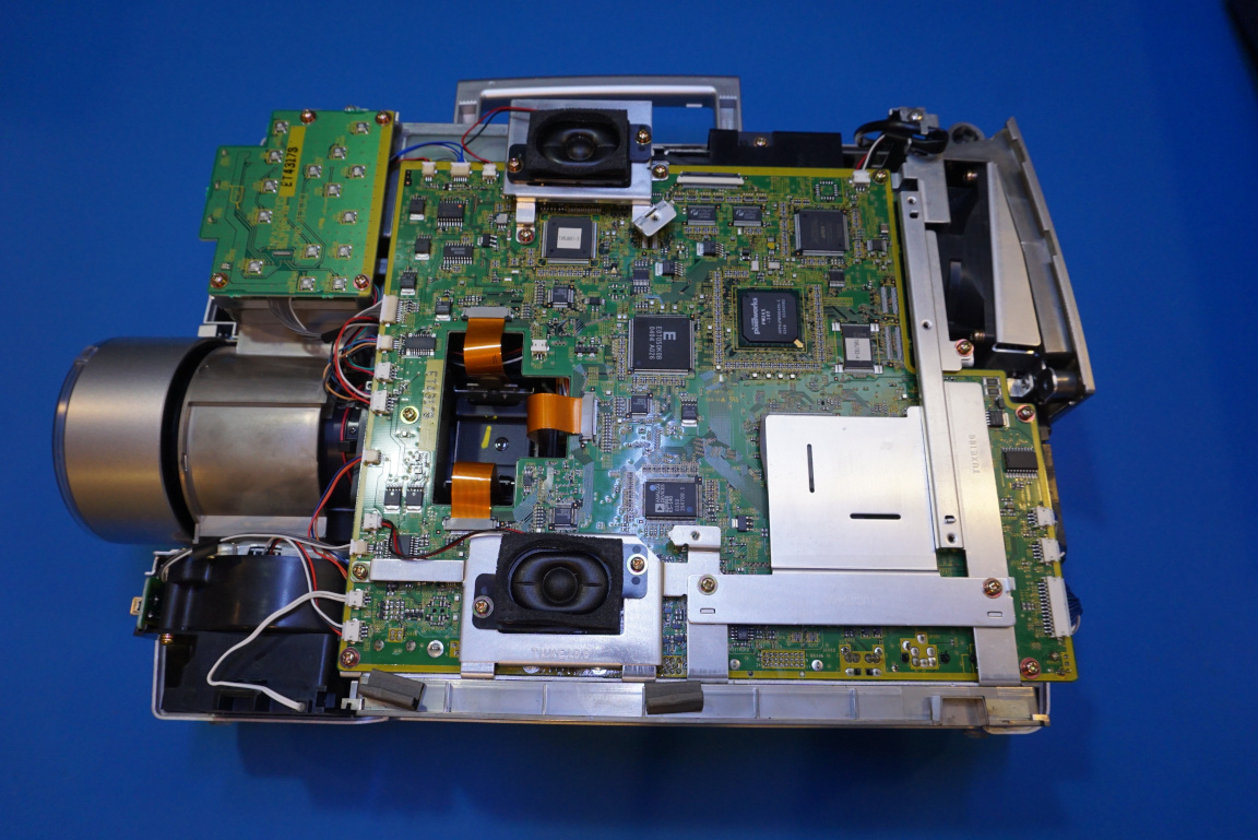
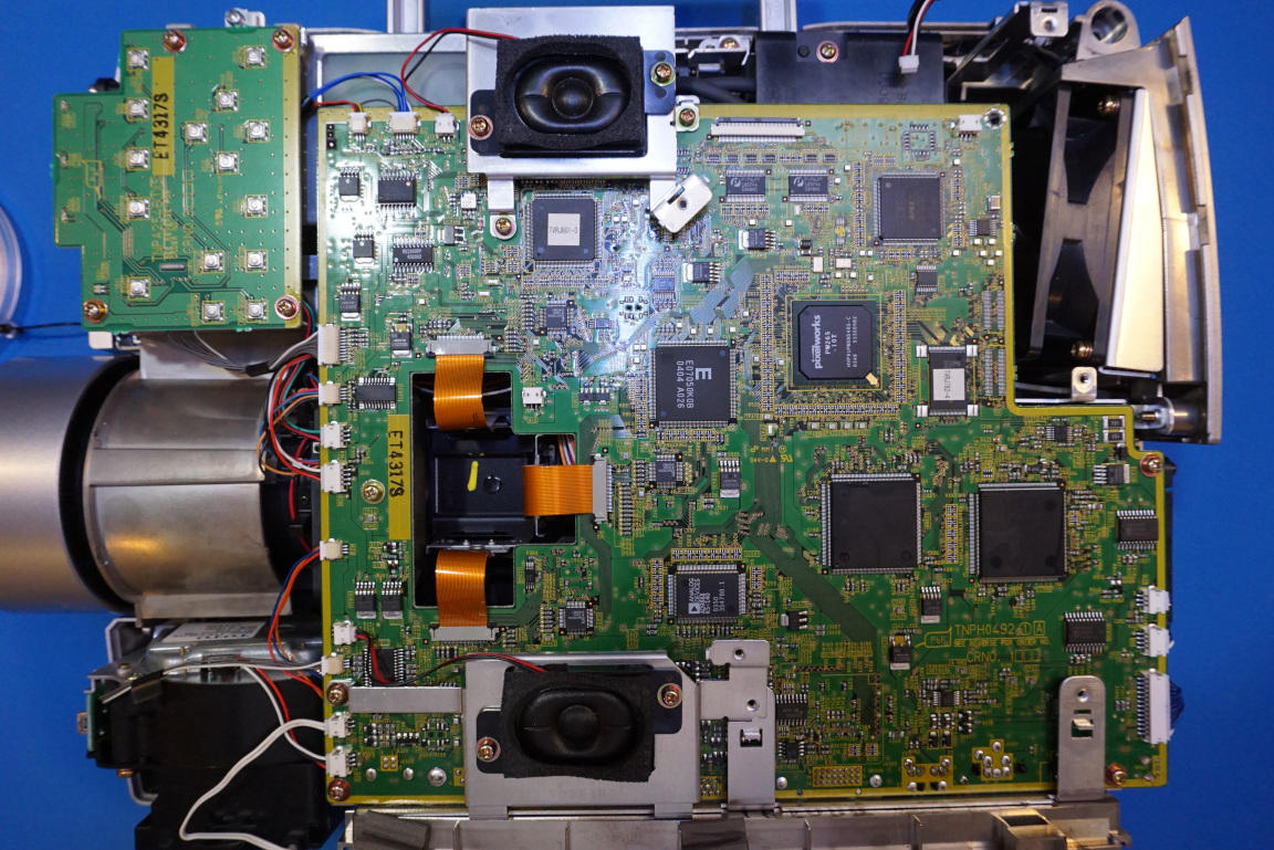
Unlike many projectors I had worked with before (for example Epson PowerLite 84 and Smart UF 55), all the electronics are enclosed within the main chassis. This means that the unit can still be operated with the cover removed since there is no electronics located within the top cover and connected from elsewhere. This turned out to be a really beneficial as we can then take a closer look at the 3LCD system in operation.
|
|
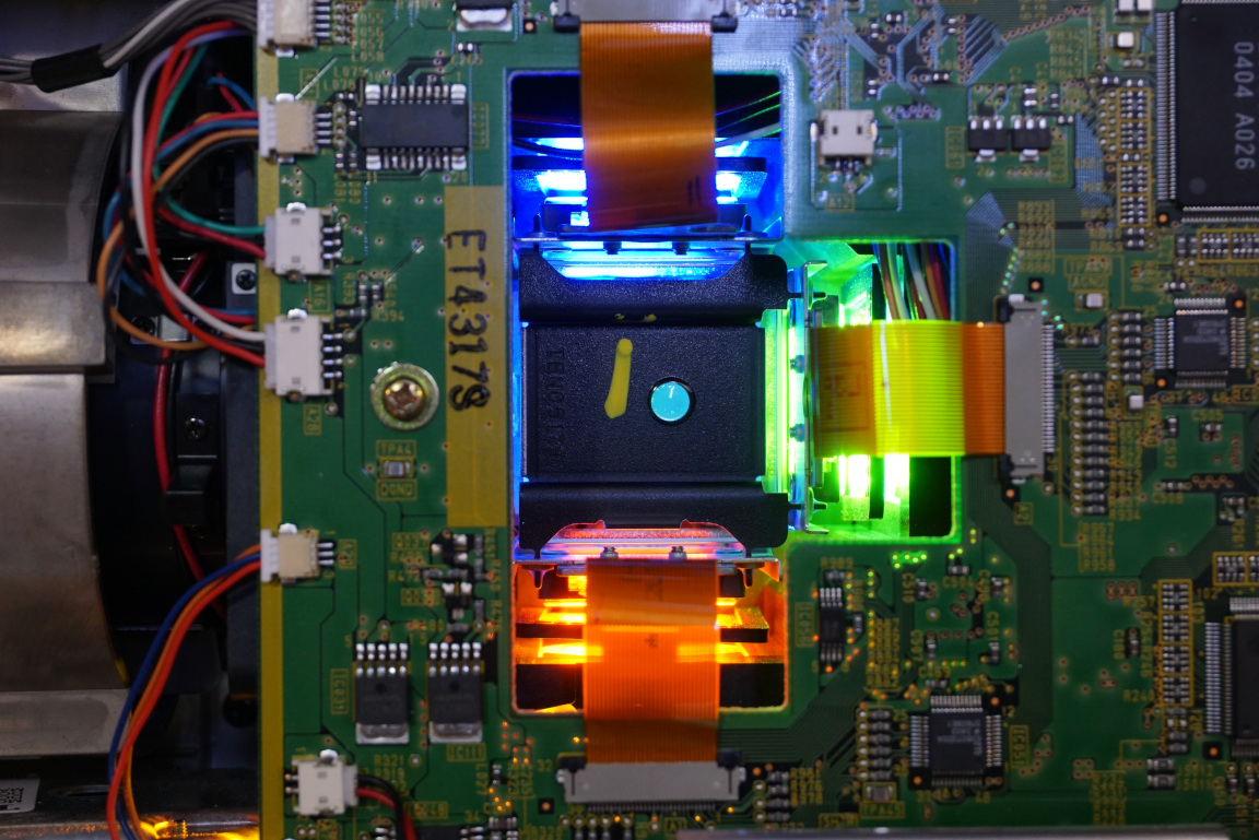
Here is a picture showing the 3LCD system in action. As the name suggested, the optical system splits the white light from the discharge projector lamp into three colored beams and each passes through an LCD that controls the image of that color component. The three (red, green, blue) colored images are then combined with a dichroic prism combiner to form the final colored image that is then projected onto the screen.
It is conceptually simple, but as you will see the implementation is fairly complicated.
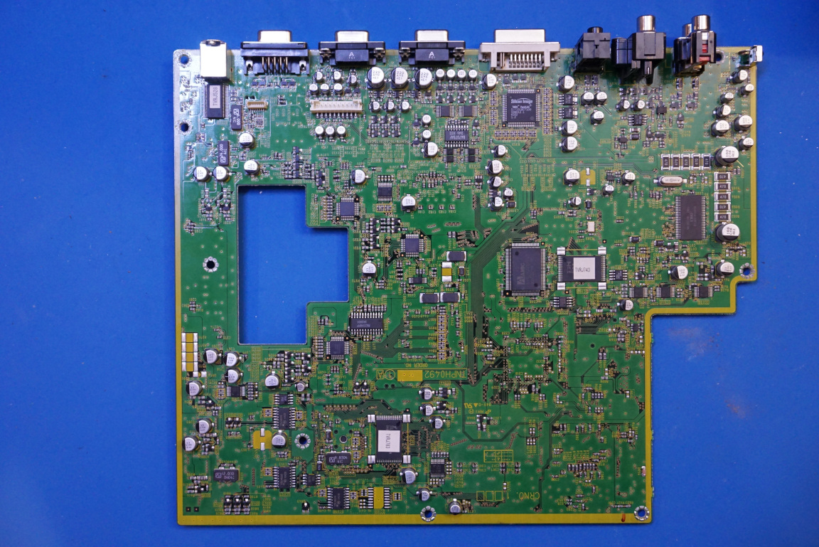
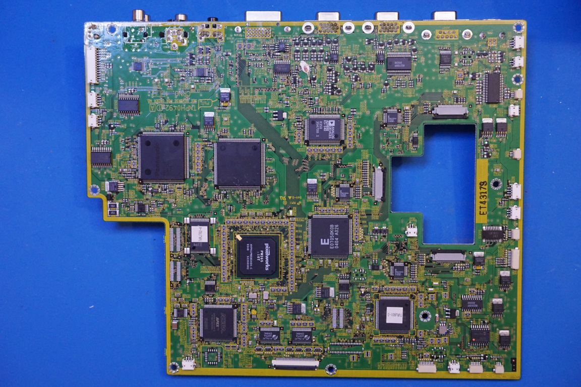
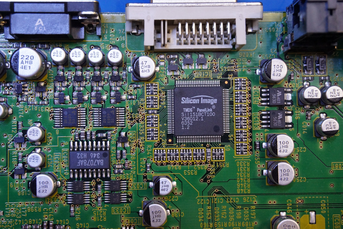
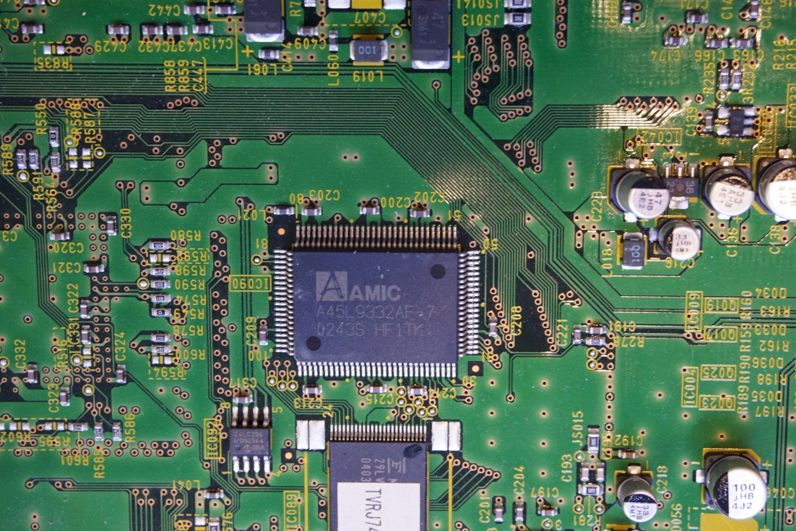
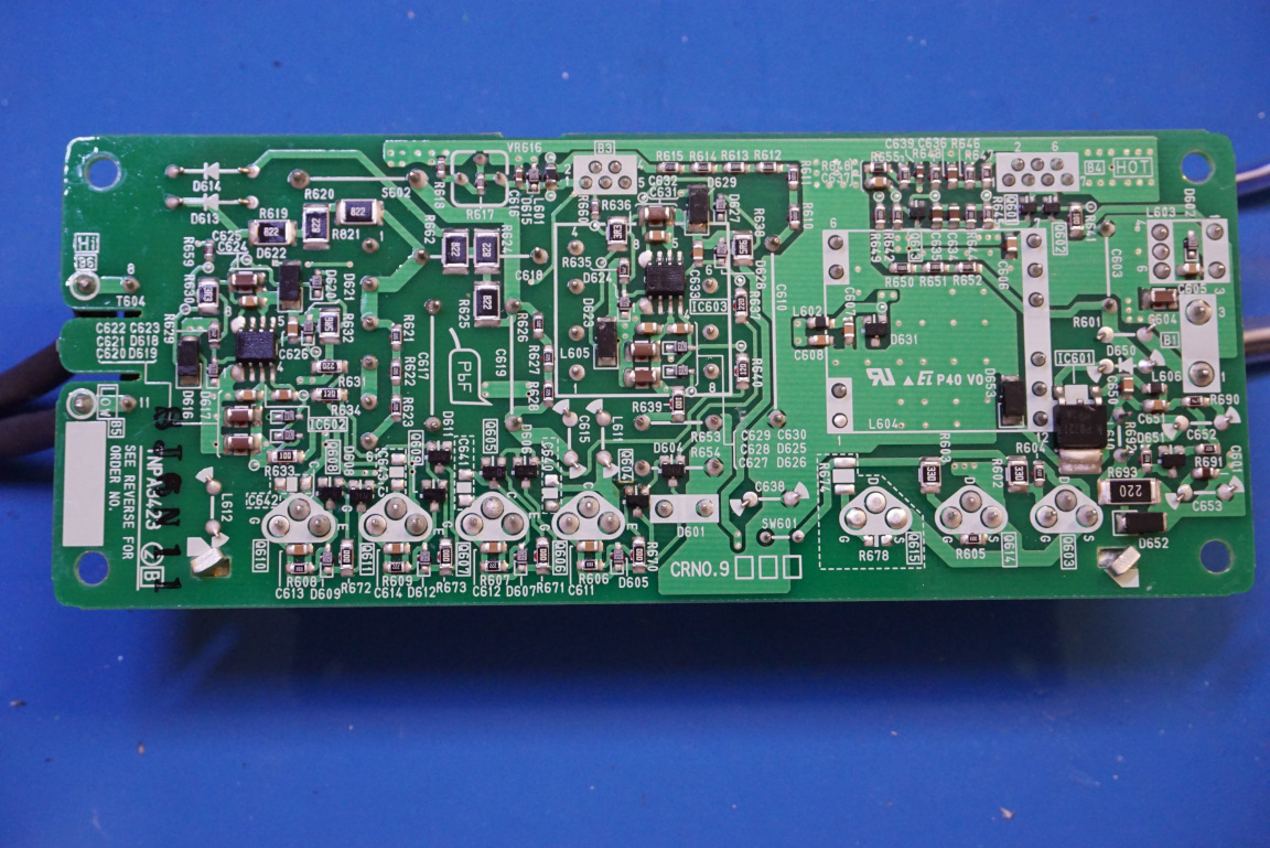
Below are two pictures showing the mainboard of the projector. As you can see, both sides are densely populated. The chip integration level back then was not as high as today’s so a lot of ICs were needed to accomplish things that could be done via a single chip nowadays.
|
|
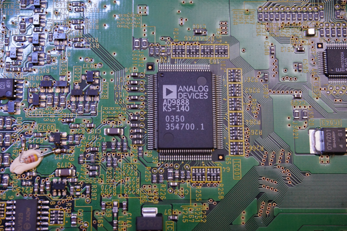
Most chips like the Pixelworks PW265-10T I could not find any information on. But it is presumably a DSP dedicated for image processing. The AD9888 is an analog flat panel interface IC for the RGB channels of the LCD projector.
|
|
|
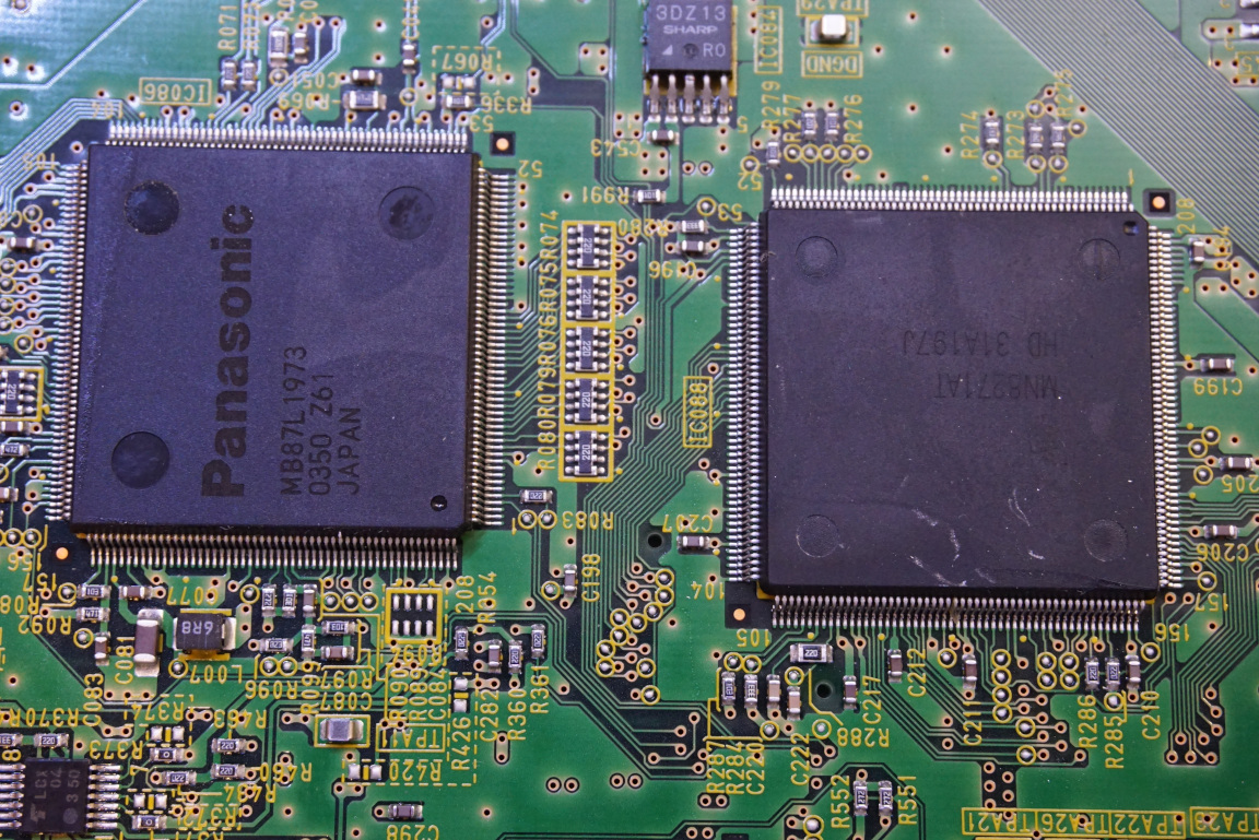
There are two heatsinked chips (one is Panasonic MB87L1973, the other one is a TI MN8271AT) but again I could not find any information on them.
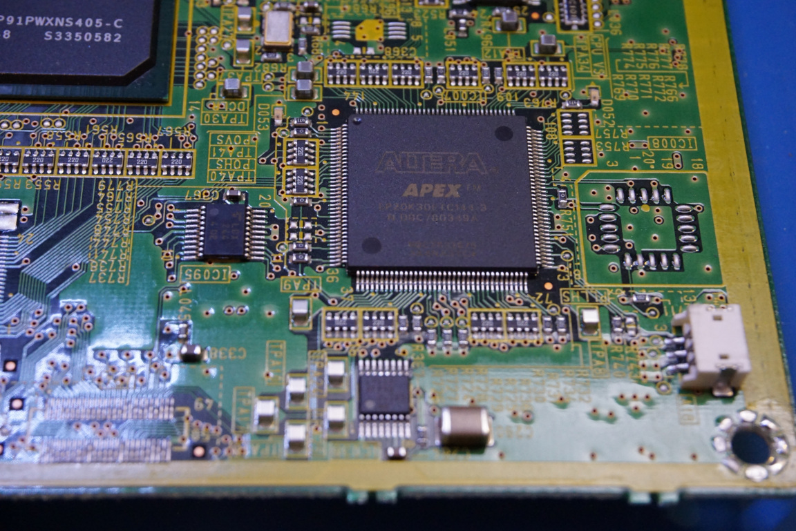
On the mainboard we can also see an Altera APEX EP20K series CPLD.
|
|
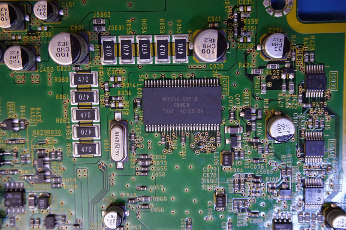
And here are a couple of pictures of the closeups on the reverse side of the motherboard, again there was no information on these chips.
|
|
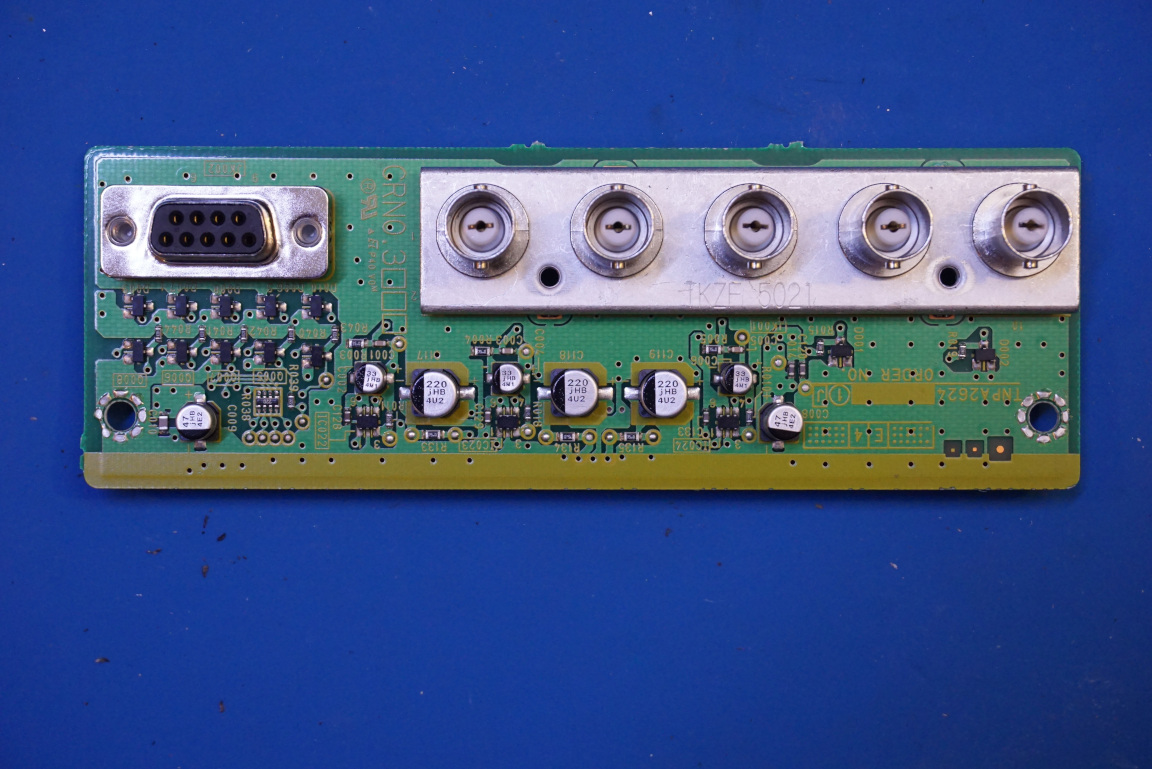
To the left below, you can see an SDRAM chip (M56v16160f-8), and to the right is the vertical board for the serial and BNC input output connectors.
|
|
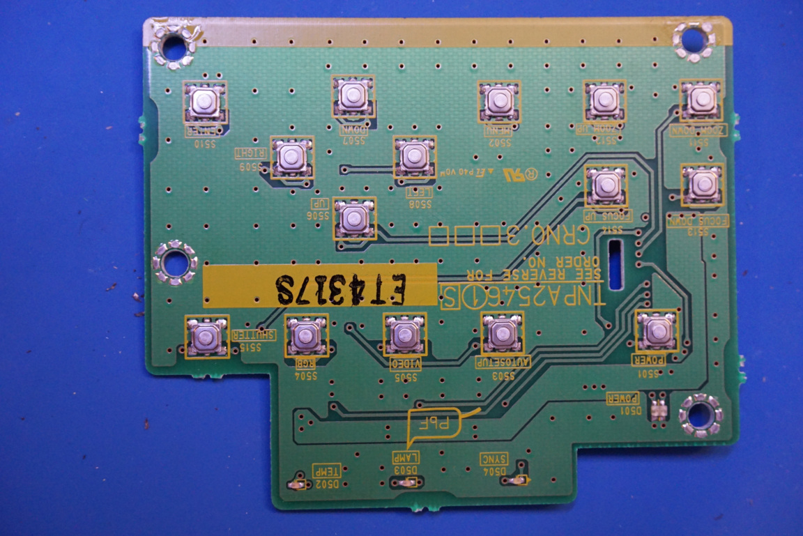
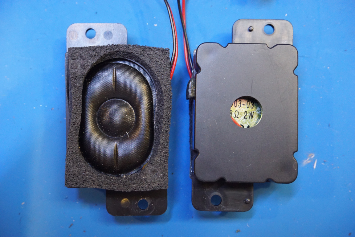
The control keypad is on its own PCB. You can also see the speakers used in this projector. They are rather tiny and are rated only for 2W each so they are mostly not designed as the main audio output.
|
|
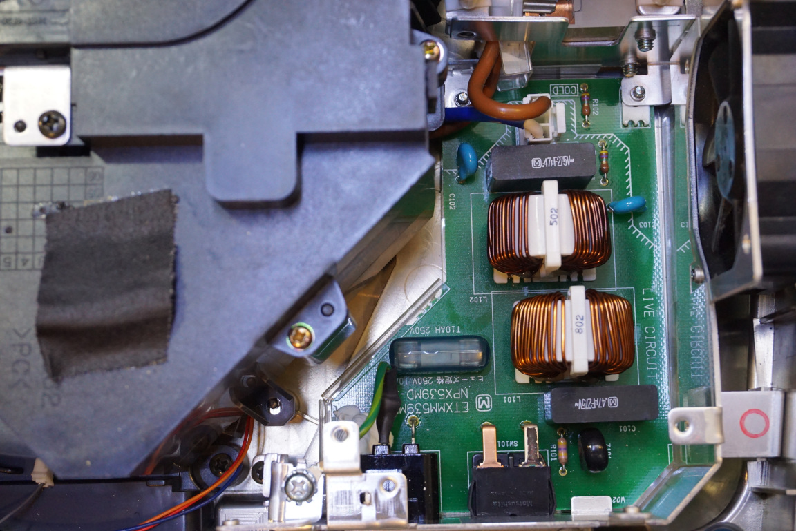
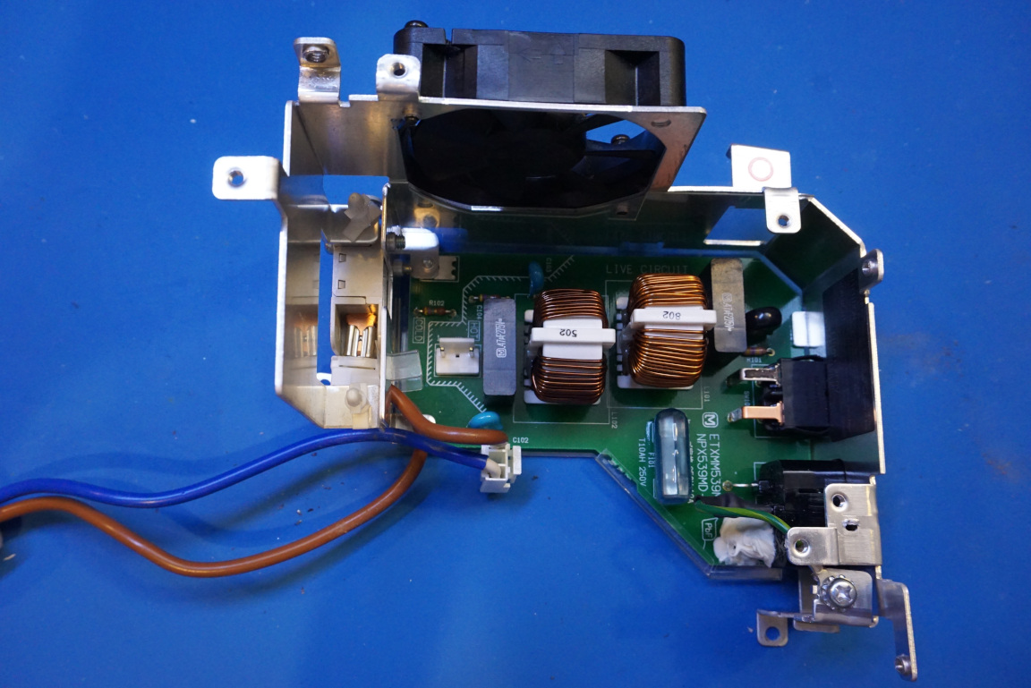
Here are a couple of pictures of the power input module. It consist of the mains IEC receptacle and switch and also has line common mode choke and filters builtin. The switching power supply is located on a separate PCB.
|
|
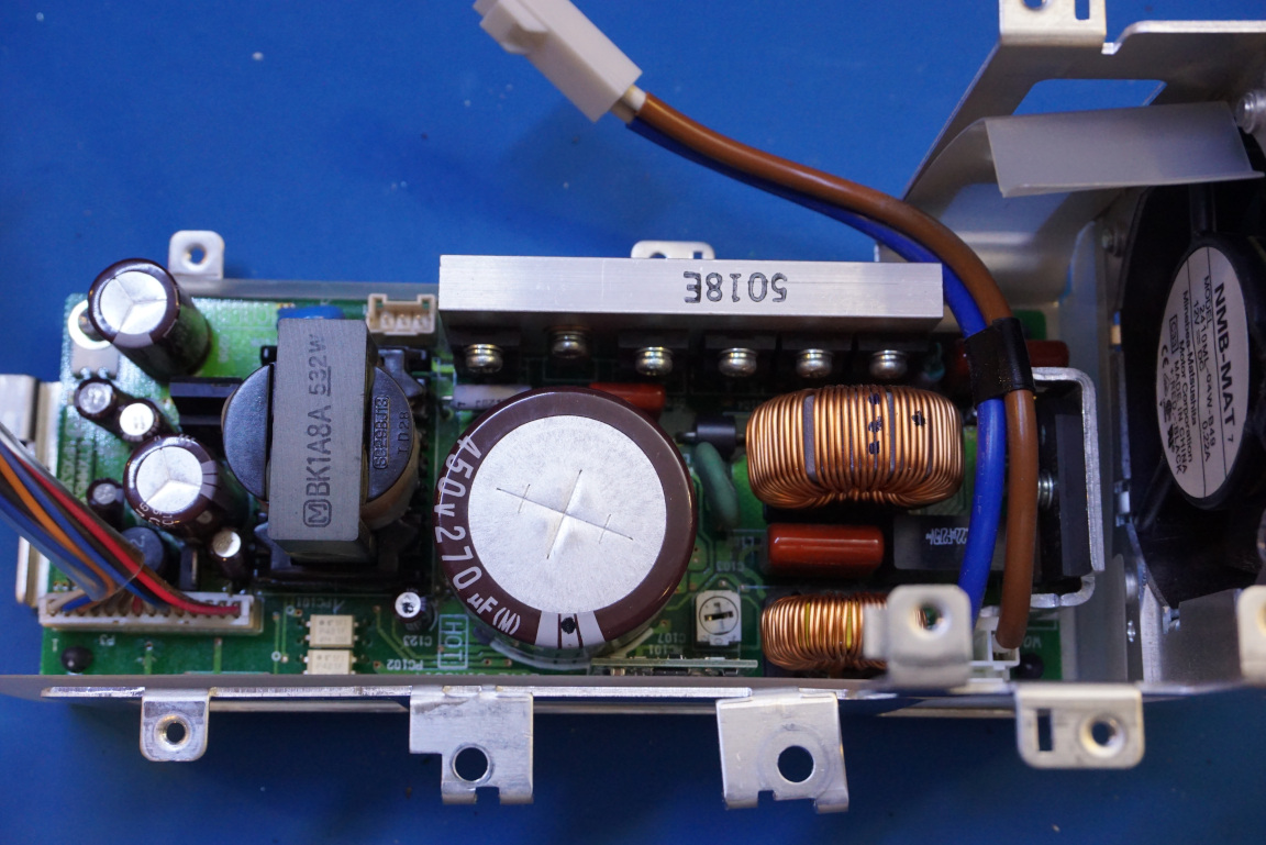
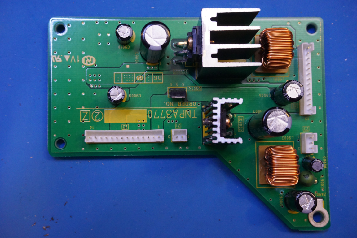
Below to the left is the main switching power supply board, it is rather compact considering that the power dissipation of the projector is rated at more than 300W. To the right is a picture of an auxiliary power module which was physically located with the power entry module and not the switching power supply module.
|
|
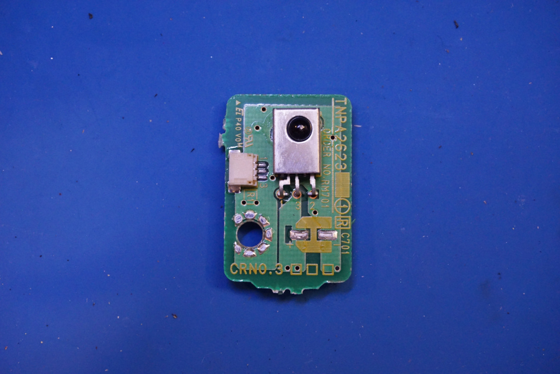
Here we have a picture of the IR sensor board. Interestingly, you can see the “missing” filter caps on many boards. It is a common practice to design boards with extra components (to improve performance margin for instance) and later in assembly, components that are not absolutely necessary can be omitted to reduce cost. This way, should the extra filter cap be needed, it can always be soldered on rather than bodged on later.
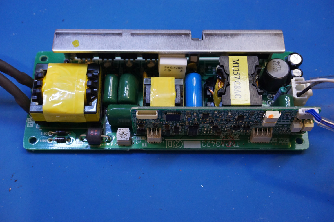
The picture to the right shows the HID lamp ballast module.
|
|
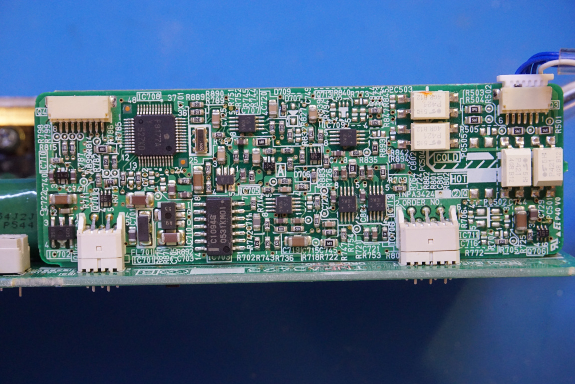
Here are a couple more pictures of the various components on the ballast board. The ballast board is typically controlled by the controller unit on the mainboard so in order to power it on outside the projector by itself some reverse engineering is needed (like what I did before for the P-VIP driver board).
|
|
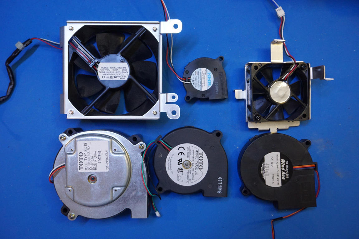
What amazes me is the number of fans used in this projector. Besides the ones on the power entry module and the switching power supply board you saw earlier, there are an additional six fans in various places. So altogether there are eight fans in this unit. No wonder the projector is so loud during operation! Since the projector was designed for commercial use, in installations in large open area I guess noise from the project is not a big concern for its intended application.
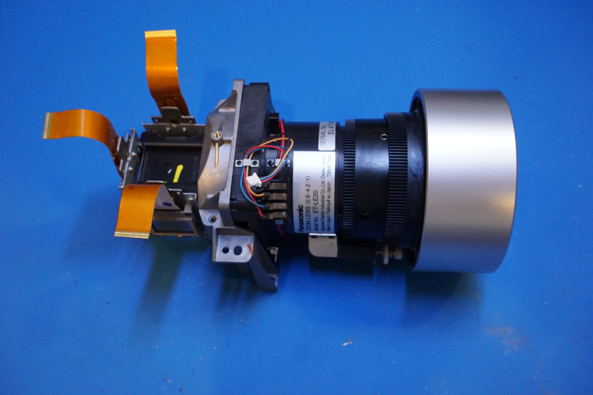
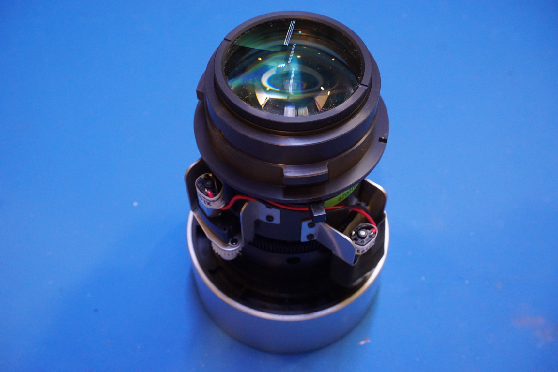
Now we move onto the optical portion of the projector. In the picture below you can see the main 3LCD assembly and projector lens assembly.
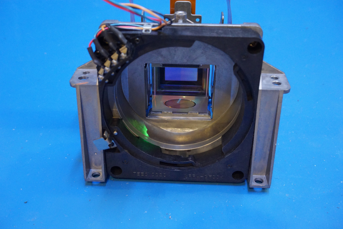
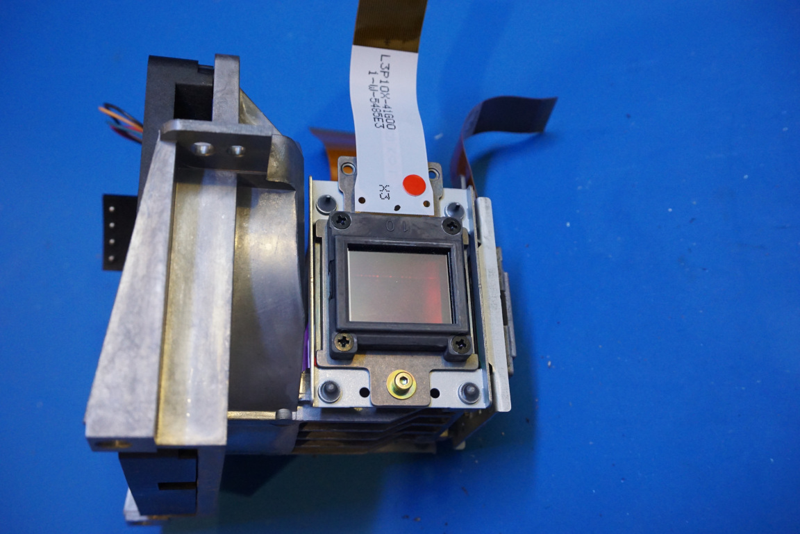
The lens portion can be detached from the 3LCD assembly. In the picture below to the left, you can see the the dichroic combiner in the middle which is responsible for combing lights coming through the three different LCDs for filtering the RGB light components.
And in the picture to the right below, you can see the LCD responsible for filtering light on the red channel to form the red image. The other two LCDs are responsible for the green and blue channels.
|
|
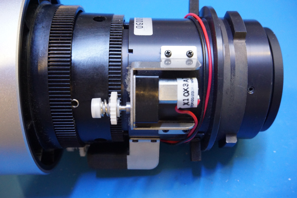
The lens assembly is fully motorized. The focus and zoom are controlled by two motors.
|
|
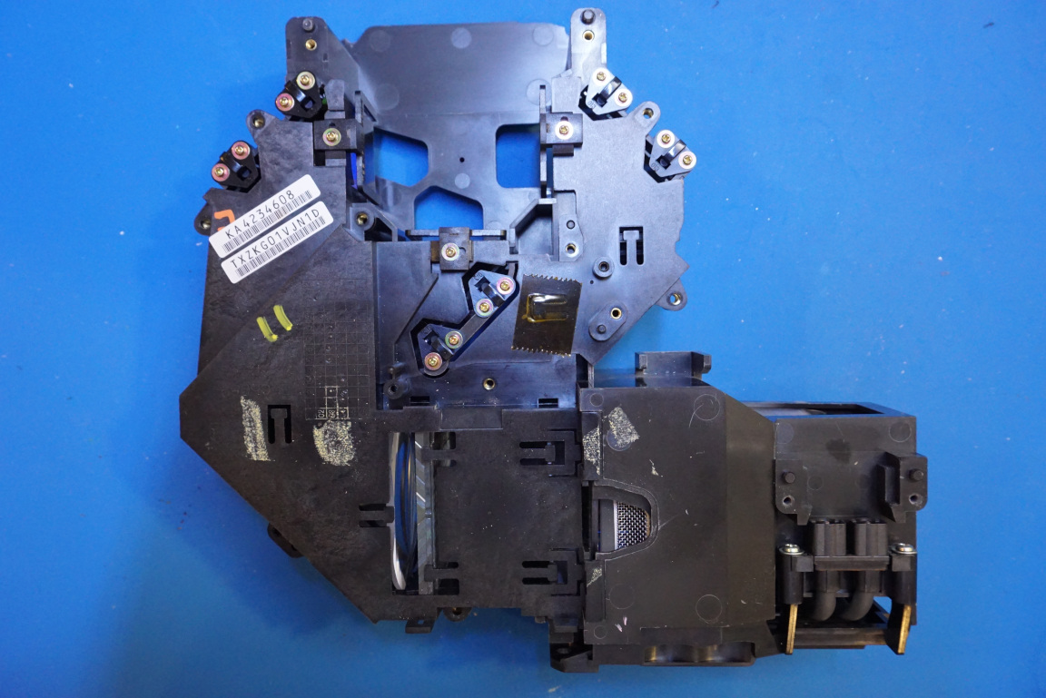
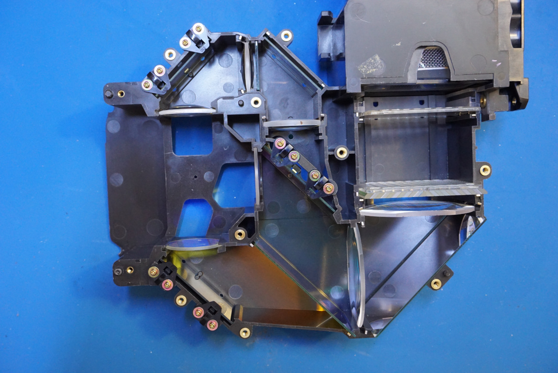
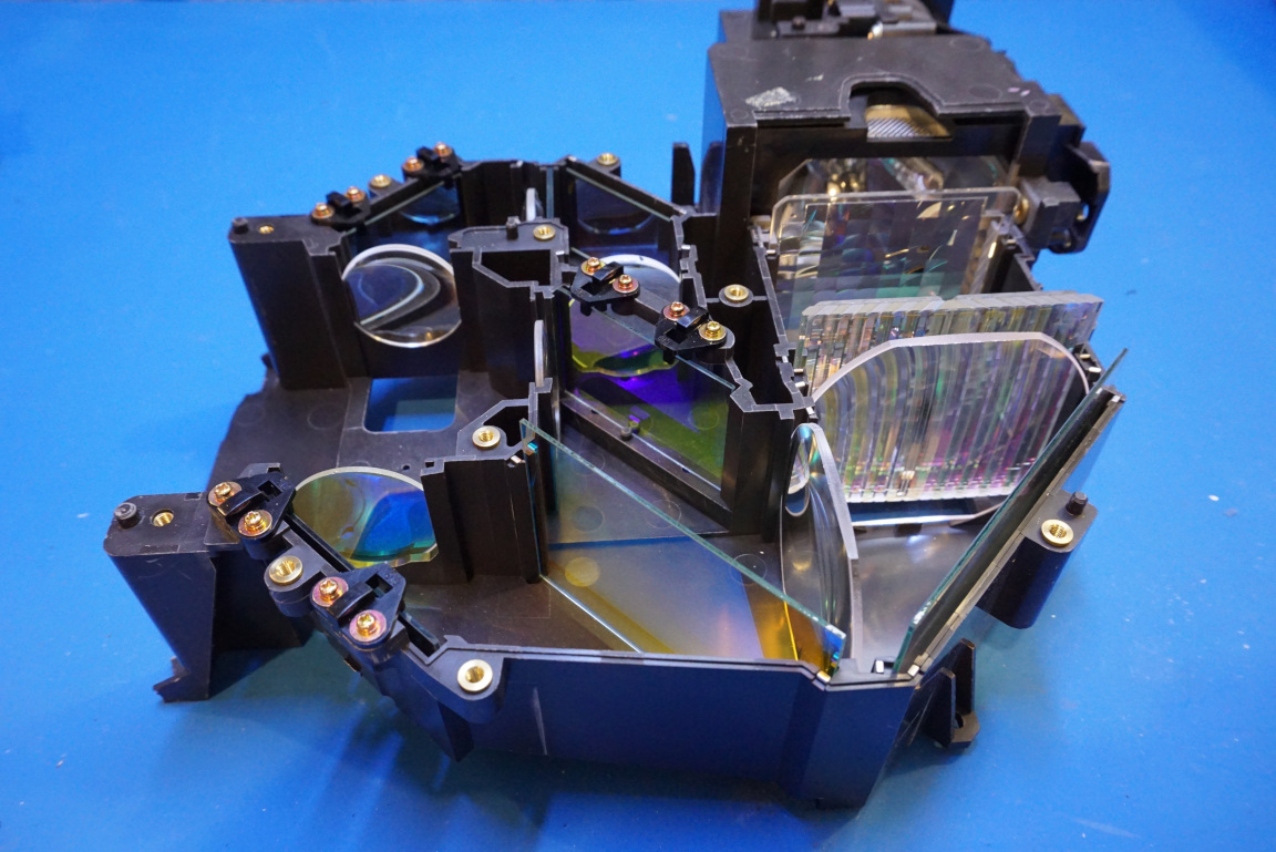
A large portion of the interior of the projector is dedicated to the following optical component, which is responsible for splitting the white light emitted from the discharge lamp into the red, green and blue components.
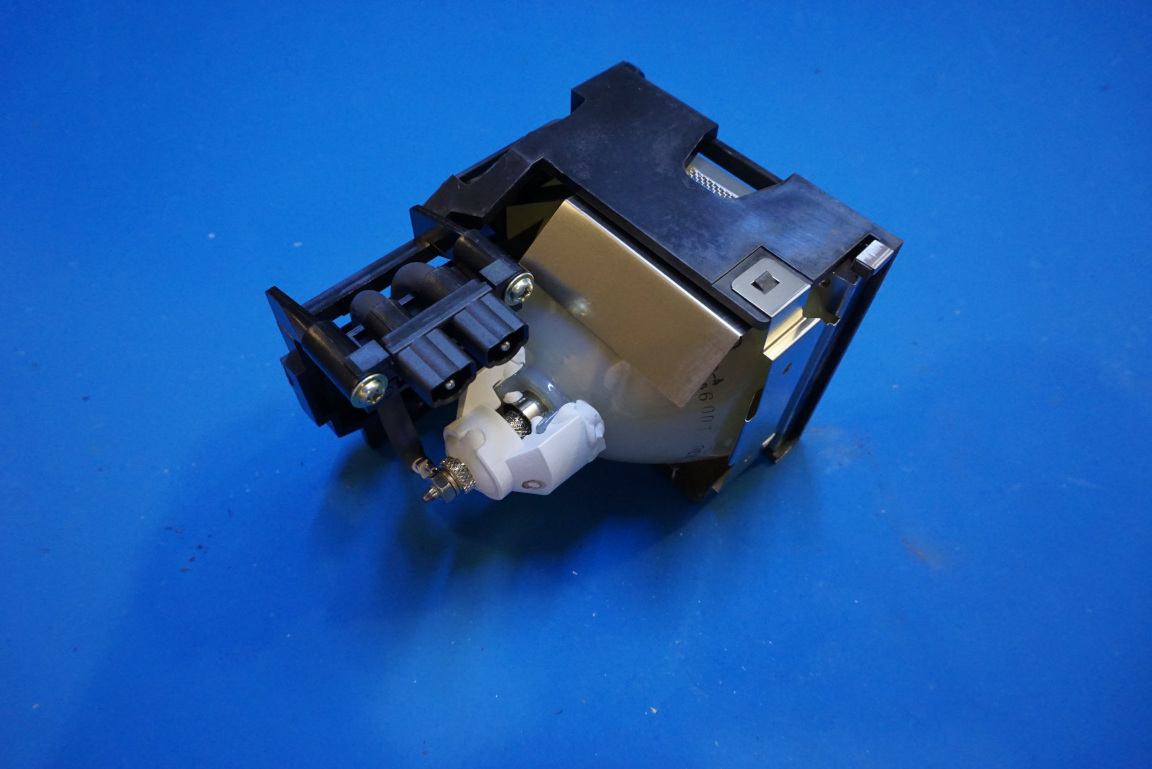
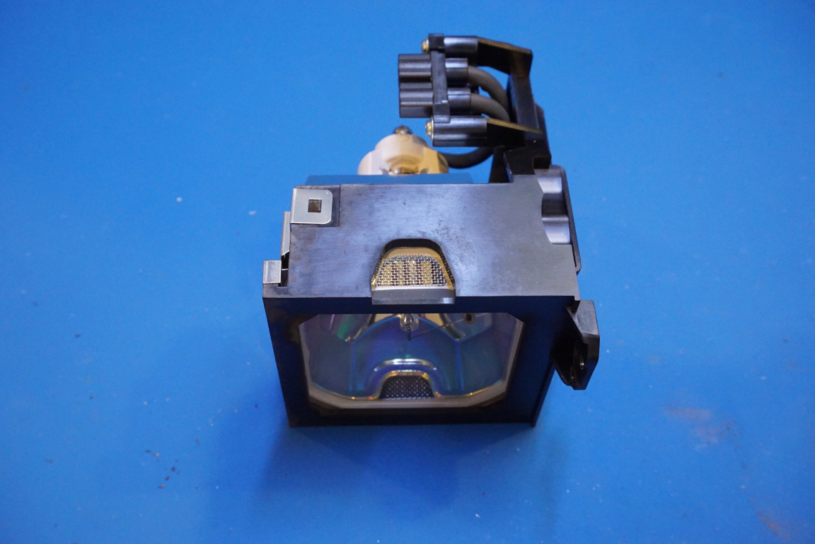
Here are a couple of pictures showing the HID lamp in its housing. The lamp runs extremely hot during operation so there are many fans placed in strategic places throughout the chassis to help dissipate the heat. Without adequate cooling things can easily become overheated and catch on fire.
Lamps are the most expensive consumables in projectors. They are typically rated for a couple of thousand hours in operation. The lamp from this unit had registered only less than 800 hours and thus still has more than half of its usable life ahead.
|
|
Here are a couple of pictures showing the optical construction of the light splitter. As you can see from the picture to the right below, light from the discharge lamp is first made uniform via two Fresnel lens, and then gets split into red green and blue components via the mirrors and lens configurations.
|
|
In the video below, you will see the teardown and some experiments done along the process.

