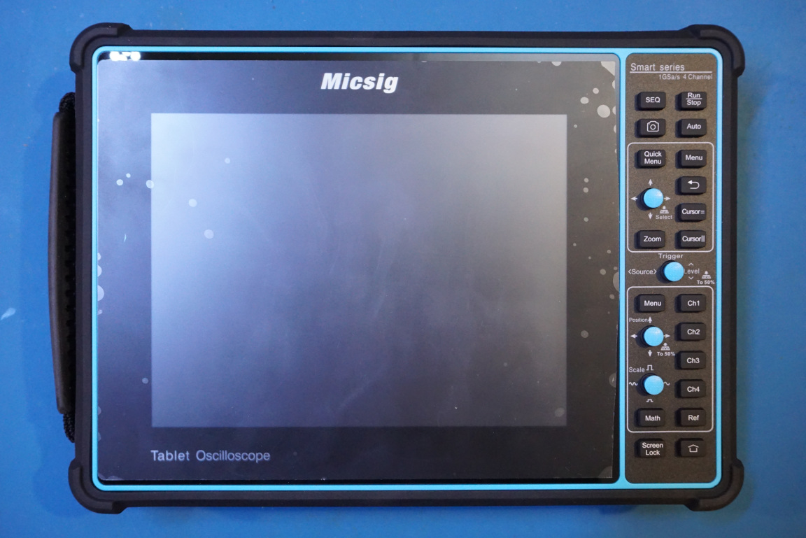
I did a thorough review of a Micsig STO1004 DSO last week. It is a powerful four channel scope taking the form of a tablet computer. This time, we will open it up and take a look inside.
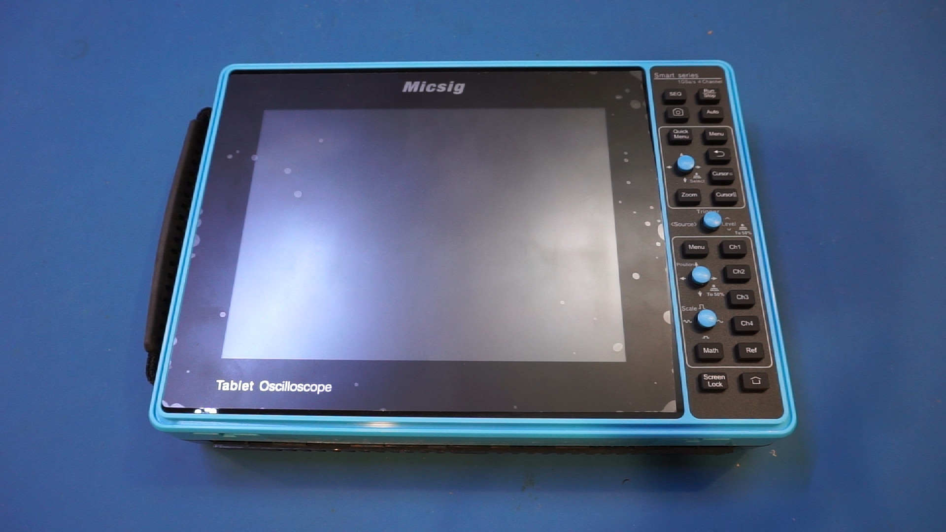
The STO1004 has a protective rubber holster, which has a very tight fit over the case. The holster needs to be removed first before all the screw holes are revealed.
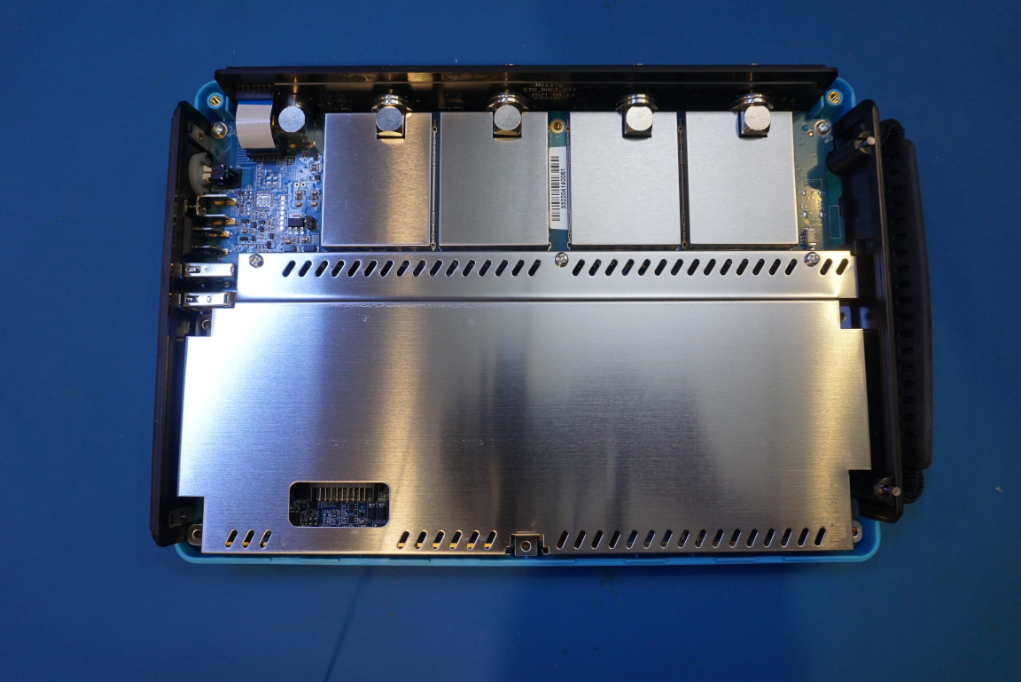
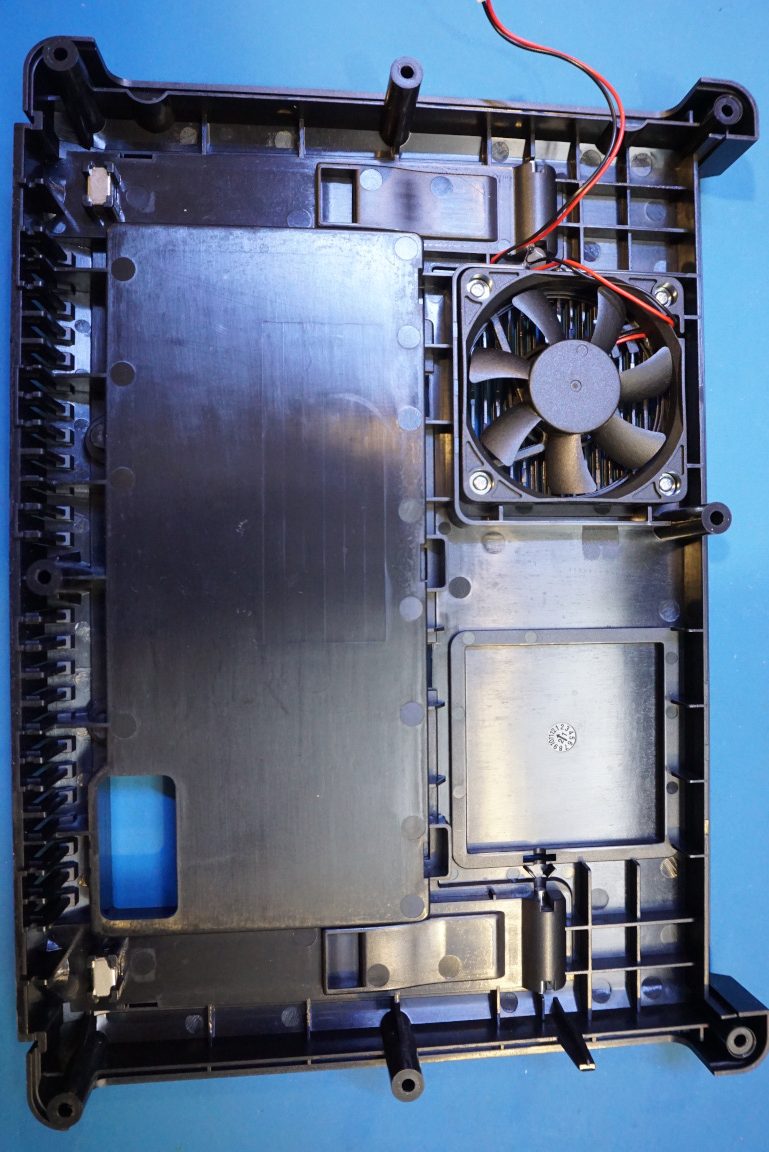
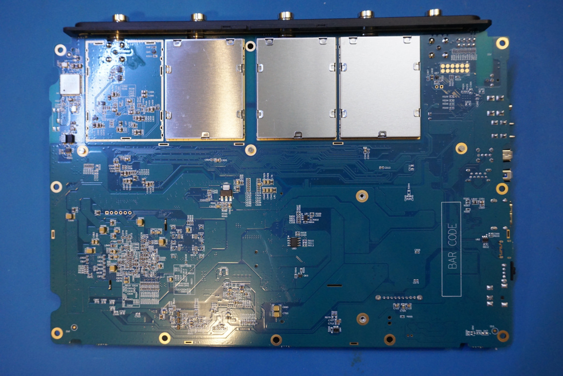
Upon removing the back cover, you will be greeted with the shielding covers. On the back cover, there is a single temperature controlled fan which kicks in during normal operations and it is relatively quiet.
Here are a couple of pictures showing the main PCB with some of the shielding covers removed. For the four input channels, I only removed the cover for channel one as the circuitry for the remaining three channels should be identical.
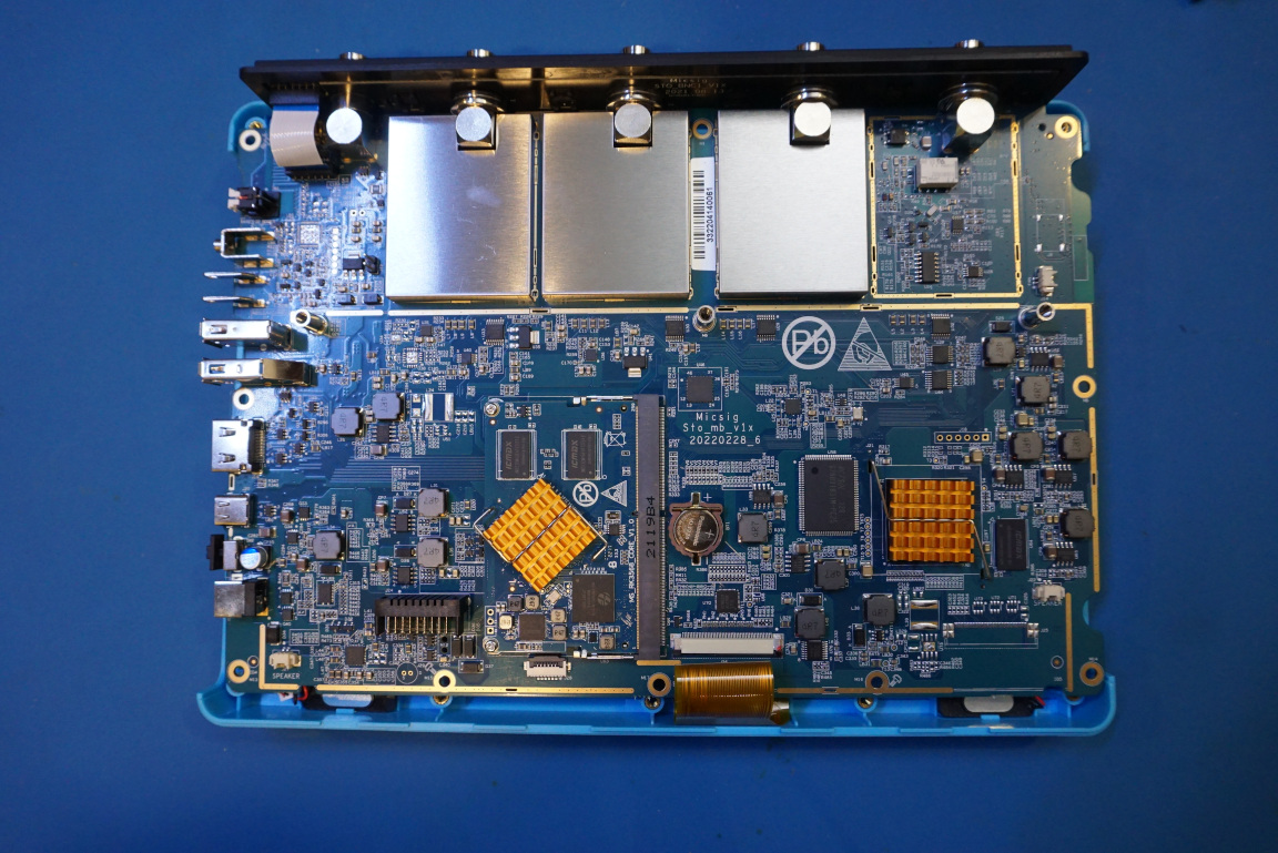
The picture below shows channel two and channel one side by side, with the channel one shielding can removed:
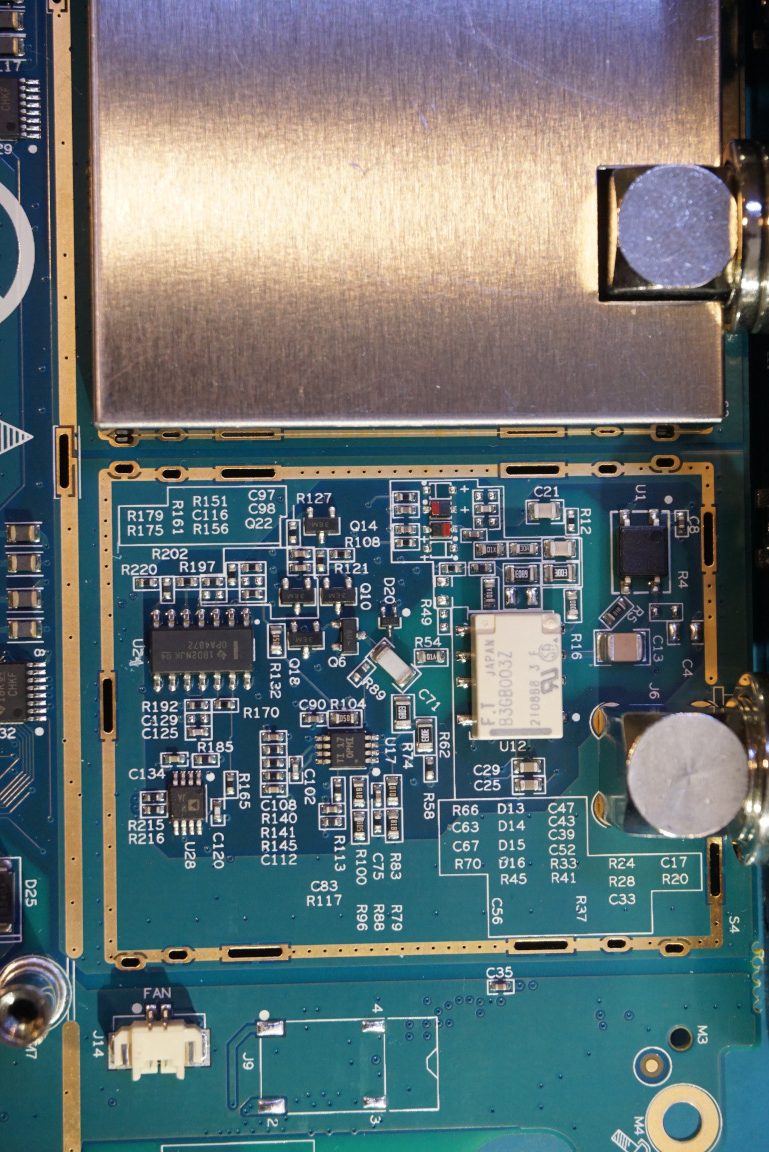
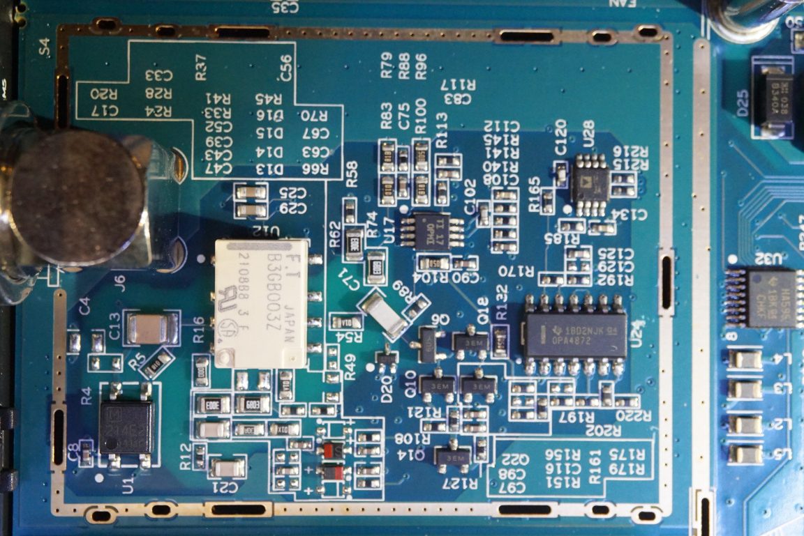
Here are a couple of pictures showing the top and bottom sides of the input section of channel one. The input stage design is rather simple. There is no trim cap or trim pot for any adjustments. The 14 pin SOIC is an OPA4872, a 500 MHz 4:1 high-speed multiplexer. The other two 8 pin SOICs are presumably high-speed OpAmps.
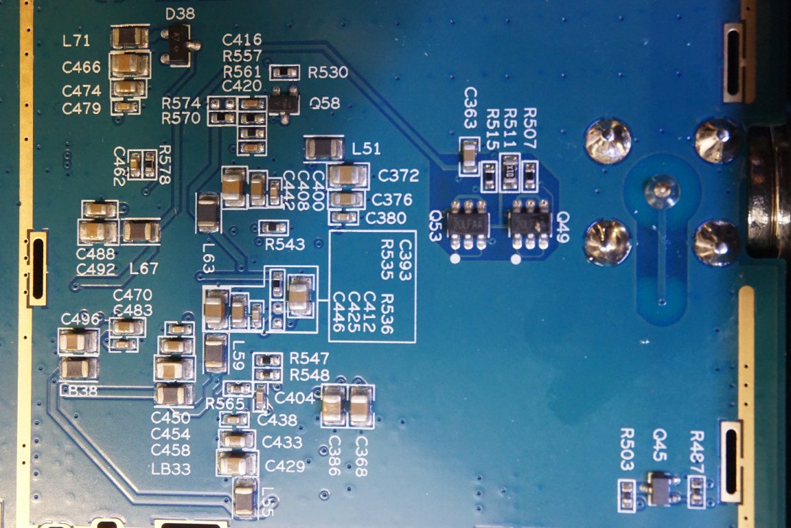
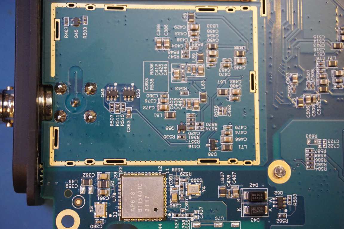
Some SMD footprints are not populated. The section next to the power switch (to the left below) seems to be the circuitry of some kind of RF module as you can see the traces of a PCB antenna. There are also a few empty footprints under the shielding can of channel four (to the right below). Not entirely sure what additional functionality was planed for.
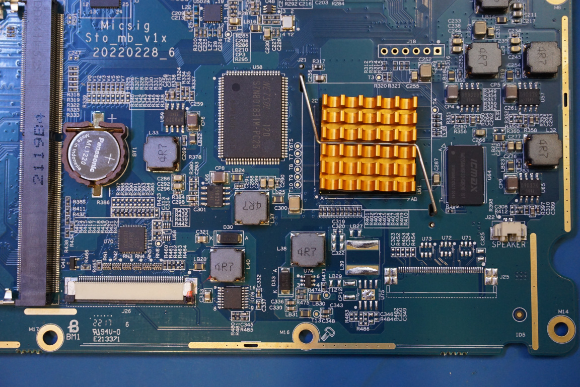
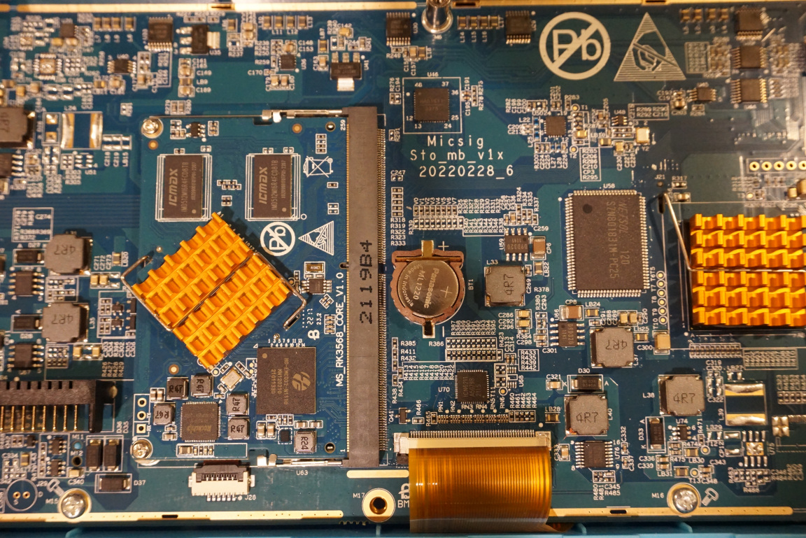
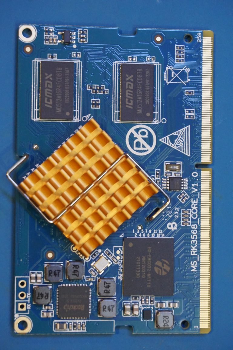
Since the oscilloscope is built ontop of Android operating system, the chip under the heatsink is most likely the main CPU. Towards the left of the CPU there is an SRAM chip and to the right there is a flash memory chip.
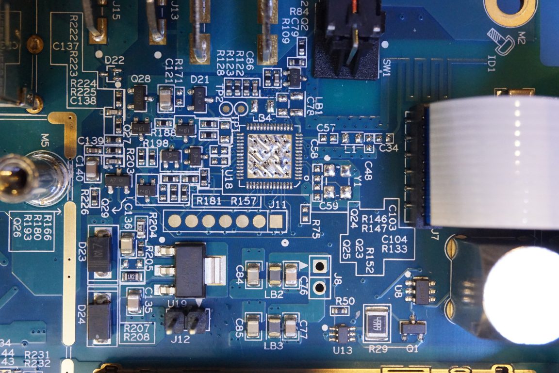
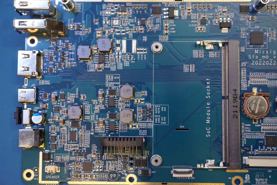
In the picture to the left below, you can see an empty footprint for what appears to be an LCD connector, perhaps this is meant for a different model of the LCD? To the right, you can see a D9D320 buck converter chip. There are quite a few of this buck converter chips throughout the board for supplying various voltages.
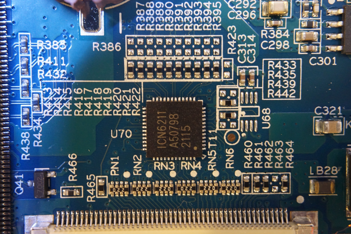
The QFN chip right above the LCD connector is an ICN6211, an MIPI DSI inputs to RGB outputs converter chip.
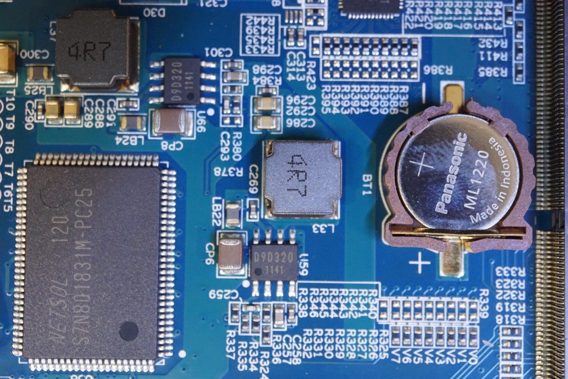
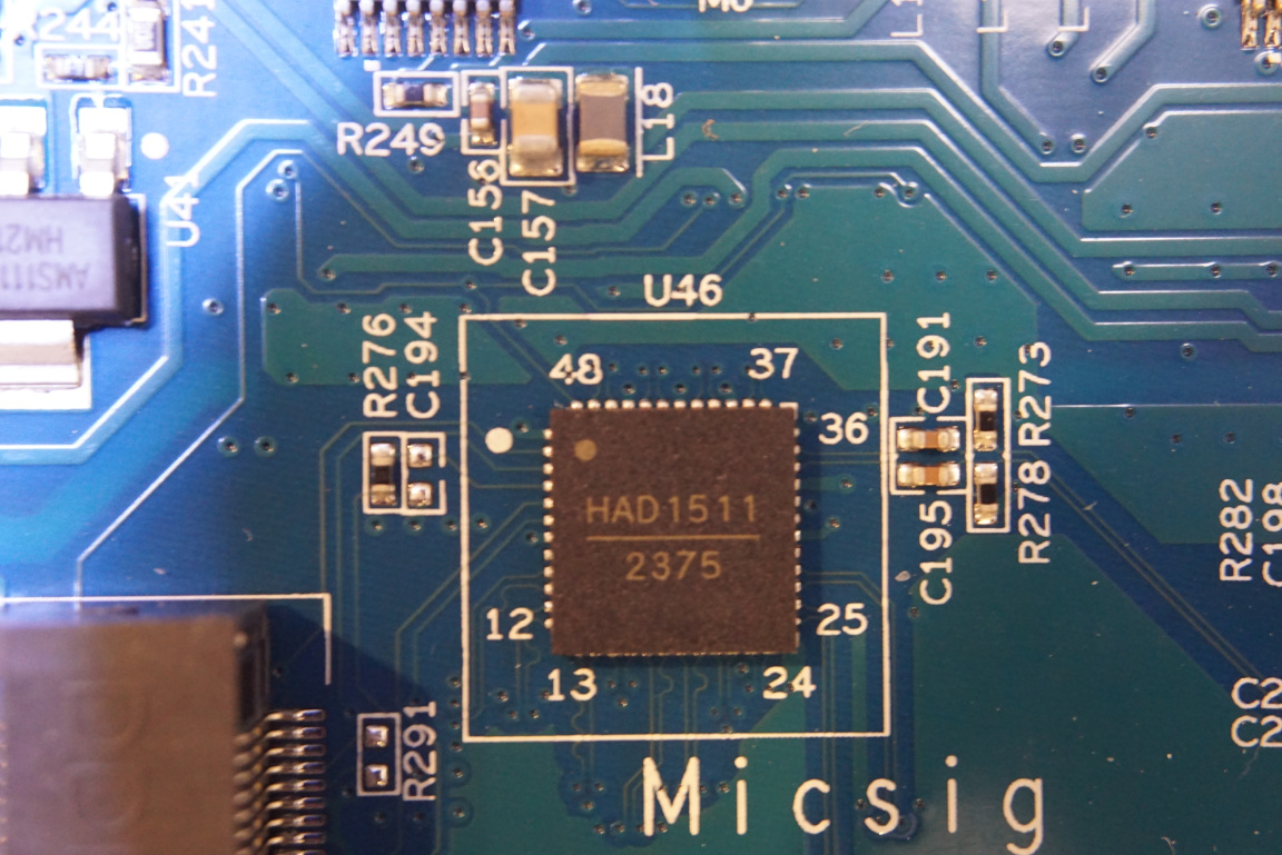
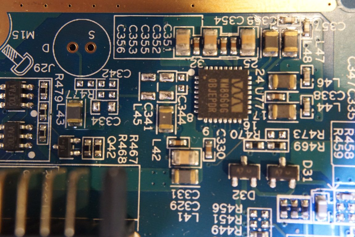
The chip right above the Micsig Sto_mb_vix 20220228_6 silkscreen is an HAD1511 (see closeup to the right), an 8 bit 30MSPS to 1GSPS A/D converter. This ADC is shared among all four input channels. Thus this scope has a sampling rate of 1 GSPS only when one channel is in use. When two channels are in use concurrently the sampling rate drops to 500 MSPS, and the sampling rate drops further to 250 MSPS when three or four channels are enabled. The smaller QFN chip to the right of the ADC is an ADF4360, an Analog Devices’ integrated synthesizer and VCO.
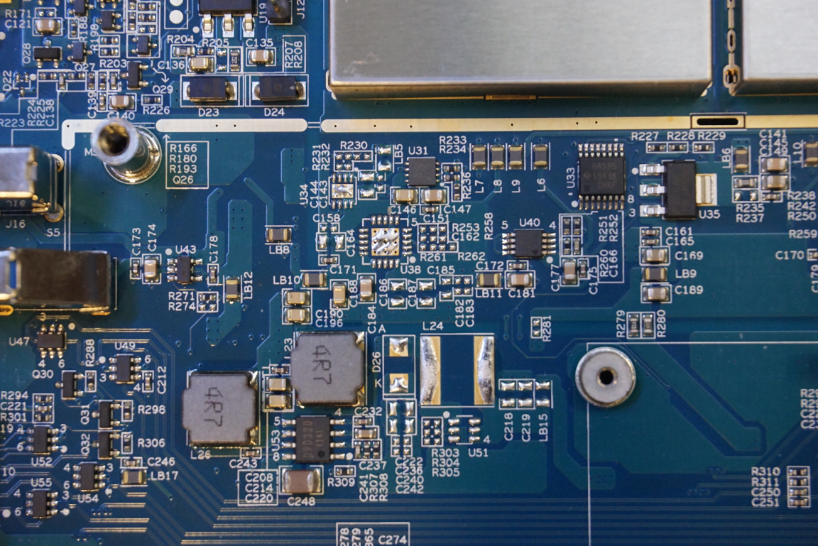
In the picture to the left below, I removed the SoC module card. You can also see quite a few D9D320 chips for different power rails. To the right, you can see a WM8960 class D amplifier that is used to drive the speakers.
My suspicion is that the SoC module contains the FPGA chip that controls the main functionality of the oscilloscope. If this is the case, it is actually quite a clever design and makes a lot of sense. Since the scope is Android tablet based, this design allows the designers to design the oscilloscope portion independently and allows for easy hardware revisions and upgrades. Well I got it reversed, the SoC module actually contains the OS the FPGA is on the main board.
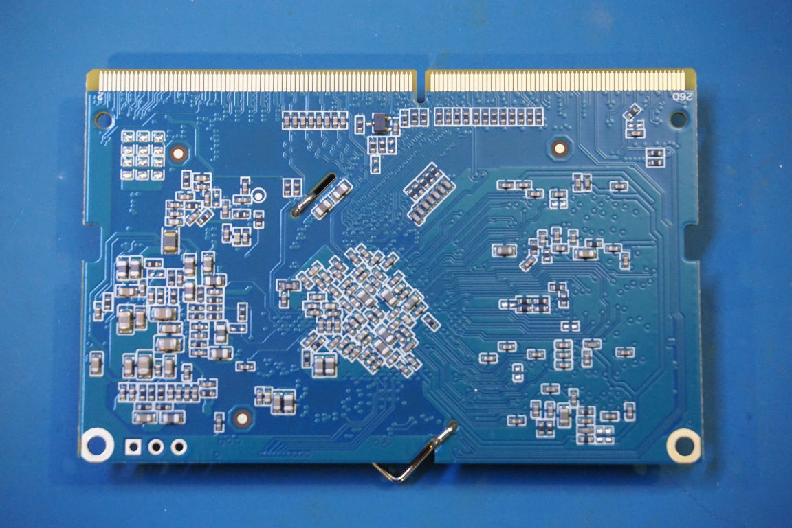
The pictures below shows both sides of the SoC module.
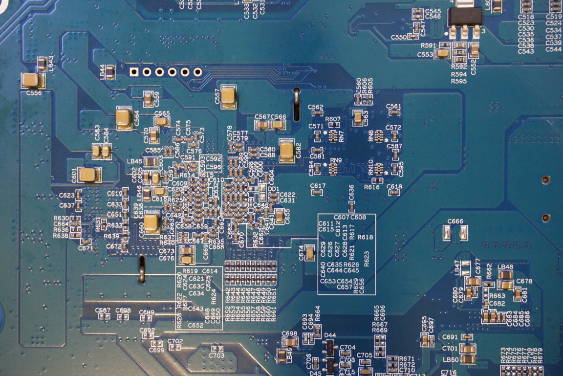
On the reverse side of the main board, there is an AP6181 WiFi module, which enables the STO1004 to connect to WiFi. The picture to the right below shows the decoupling capacitors on the reverse side of the main CPU along with a JTAG test header.
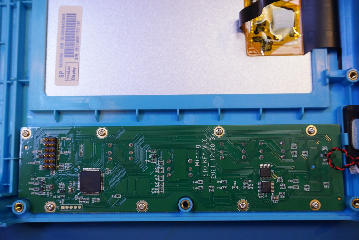
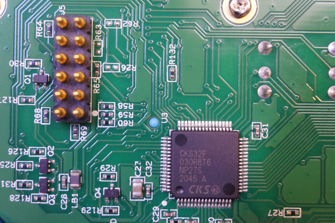
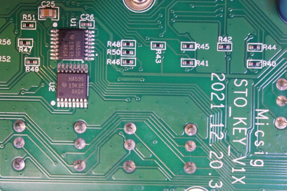
On the front panel section, there is a separate board for controlling the keypad. There is an STM32 compatible MCU (CKS32F030)on the PCB along with a couple of 595 shift registers.
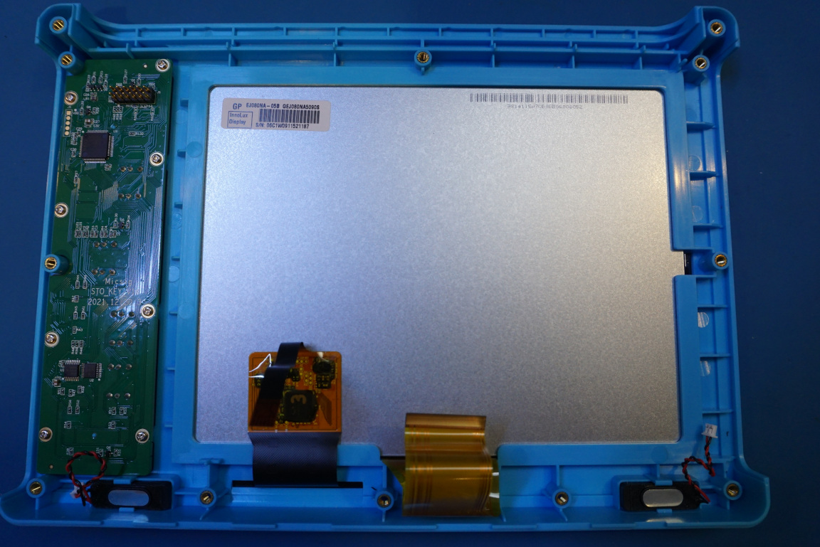
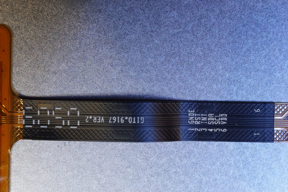
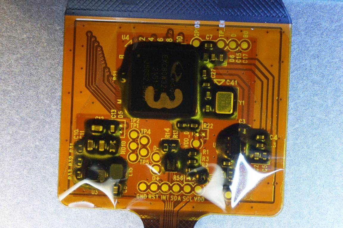
The touch interface appears to be controlled by I2C according to the cable pinout. The touchscreen controller in use is an EXC80W32.
Here is a video of the teardown.

