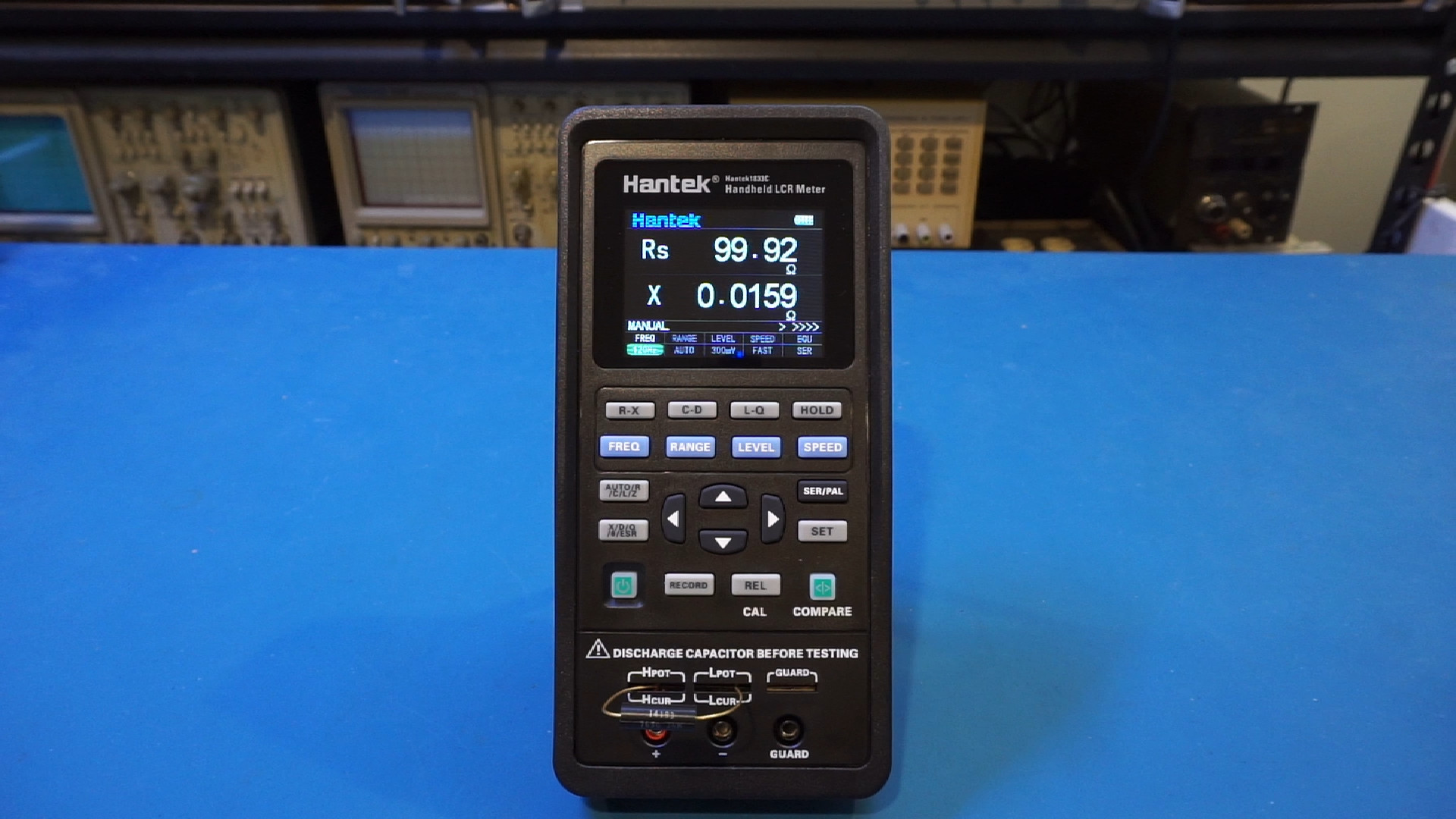
A dedicated LCR meter is a luxury for many electronics hobbyists, but it is extremely useful when dealing with analog circuitry where the component values need to be known precisely under the given frequency conditions. I have an Agilent 1731B in my lab and had been using it for many years. In this blog post, we will take a look at the internals of a Hantek 1833C handheld LCR meter. A detailed review video is linked towards the end of the post.
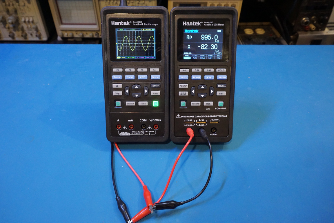
The physical appearance of the Hantek 1833C is very similar to that of the 2D72 oscilloscope as they utilize almost the identical case designs.
There are two versions of the LCR meter in Hantkek’s 183X line-up. The 1832C and the 1833C. The only noticeable differences between these two models are the additional measurement frequencies for the Hantek 1833C (75 kHz and 100 kHz) and one additional signal output level (0.3V), the remaining specifications are identical between these two models.
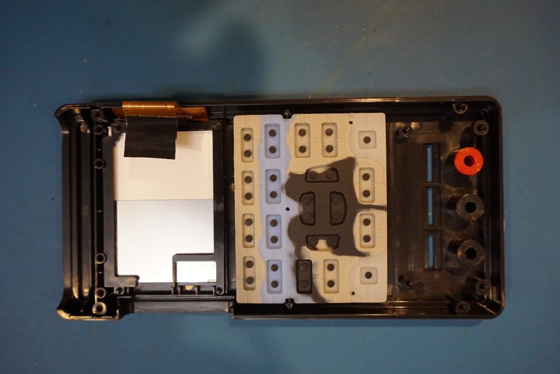
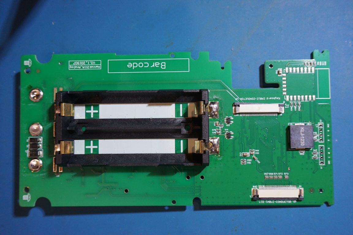
The internal layout of the 1833C is considerably cleaner compared to the 2D72 given that the circuitry for an LCR meter is much simpler than an oscilloscope. It utilizes a two-PCB design, one is the keypad board (see below) and the other is the main PCB.
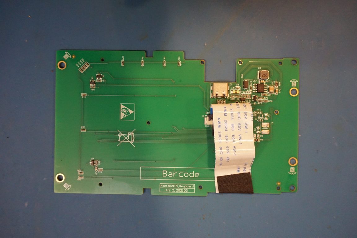
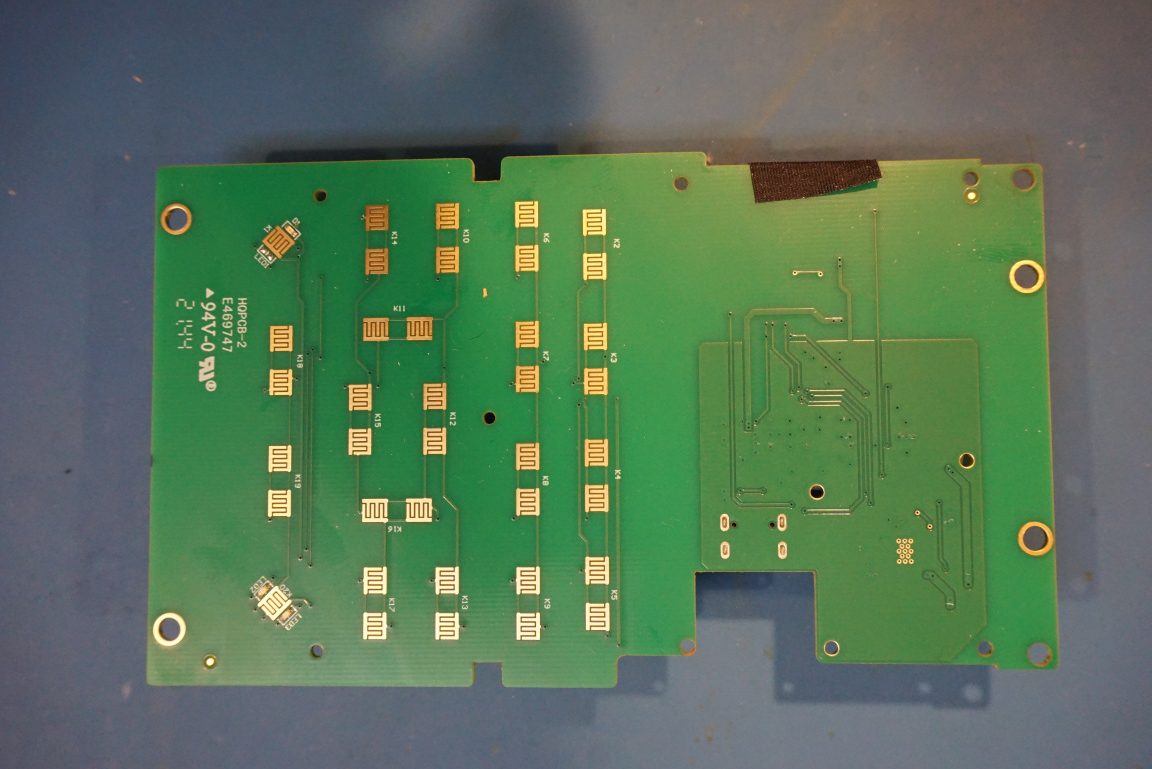
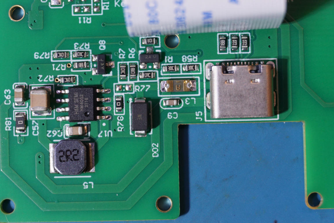
The only active circuitry on the keypad board is for battery charging. This is accomplished by the HM4052 charging controller.
Here are a couple of pictures of the main PCB. Like the 2D72, the 1833C PCB also has a foot print for an SD card but that footprint is unpopulated.
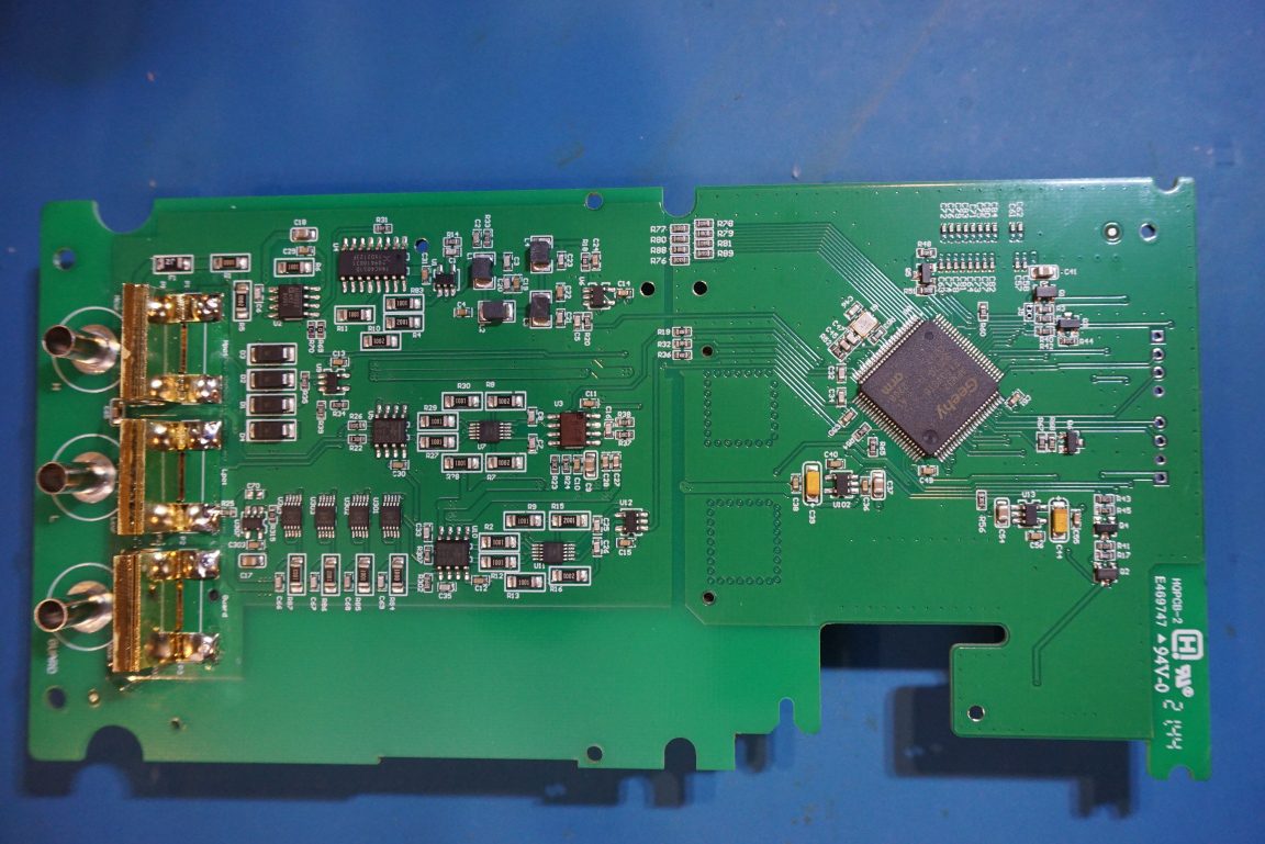
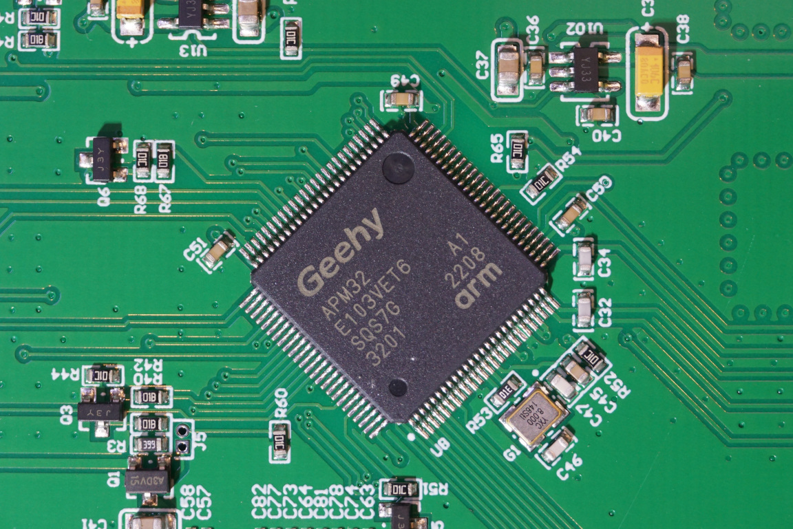
The main processor used in this LCR meter is a Geehy APM32E103 ARM Cotex M3 compatible microprocessor.
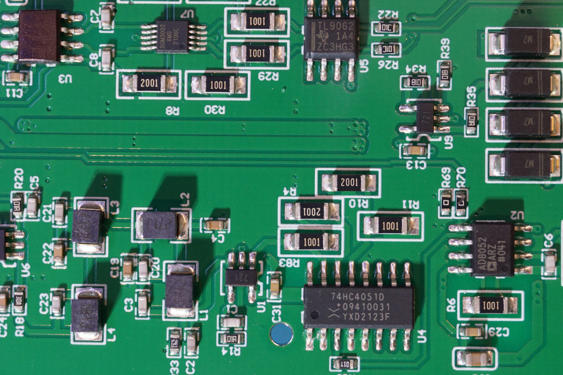
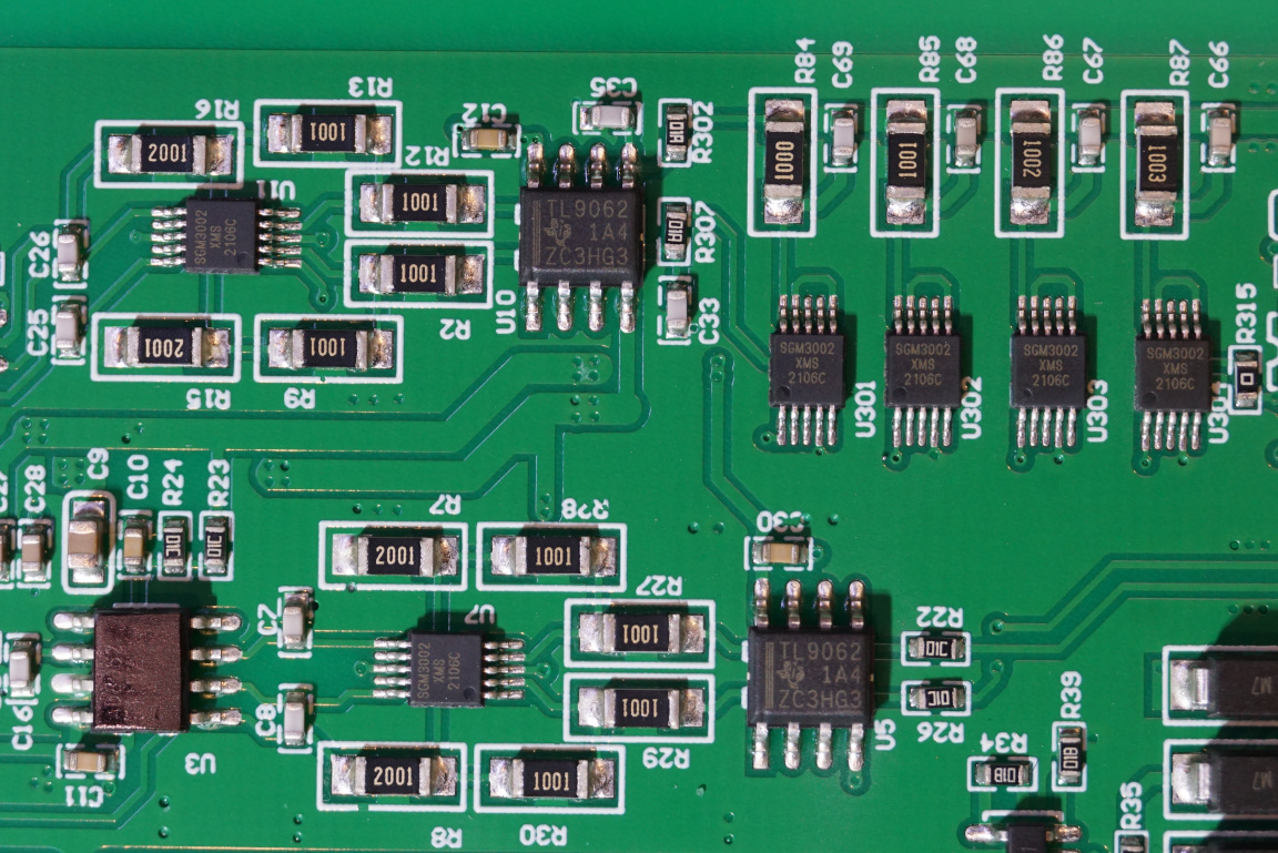
Other components include TL9062 Opamps, AD8052 high-speed Opamps, 74HC4051 mux and SGM3002 SDPT analog switch ICs.
It is clear that all the major functionalities are accomplished by the MCU given the supporting circuitry we see.
Stephan Rautenberg reverse engineered the schematics, you can find his work here:

