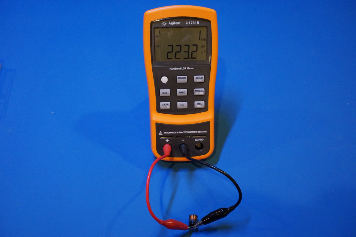
A couple of weeks ago, I got myself an Agilent U1731B LCR meter on eBay. These handheld LCR meters are quite expensive when new, but can be found on eBay for a fraction of the original price. Dave Jones at the EEVBlog did a teardown video on a better spec’d U1733C (and U1733B) meter a few years ago, I suspect that circuit-wise the U1731B would be quite similar to what’s inside of a U1733B.
Once the back cover has been removed, it became clear that indeed the circuit board looks very similar to that of the U1733B. This should not be a surprise though as both U1731B and U1733B are quite similar in terms of functionality, with U1733B offers slightly better range and specs.
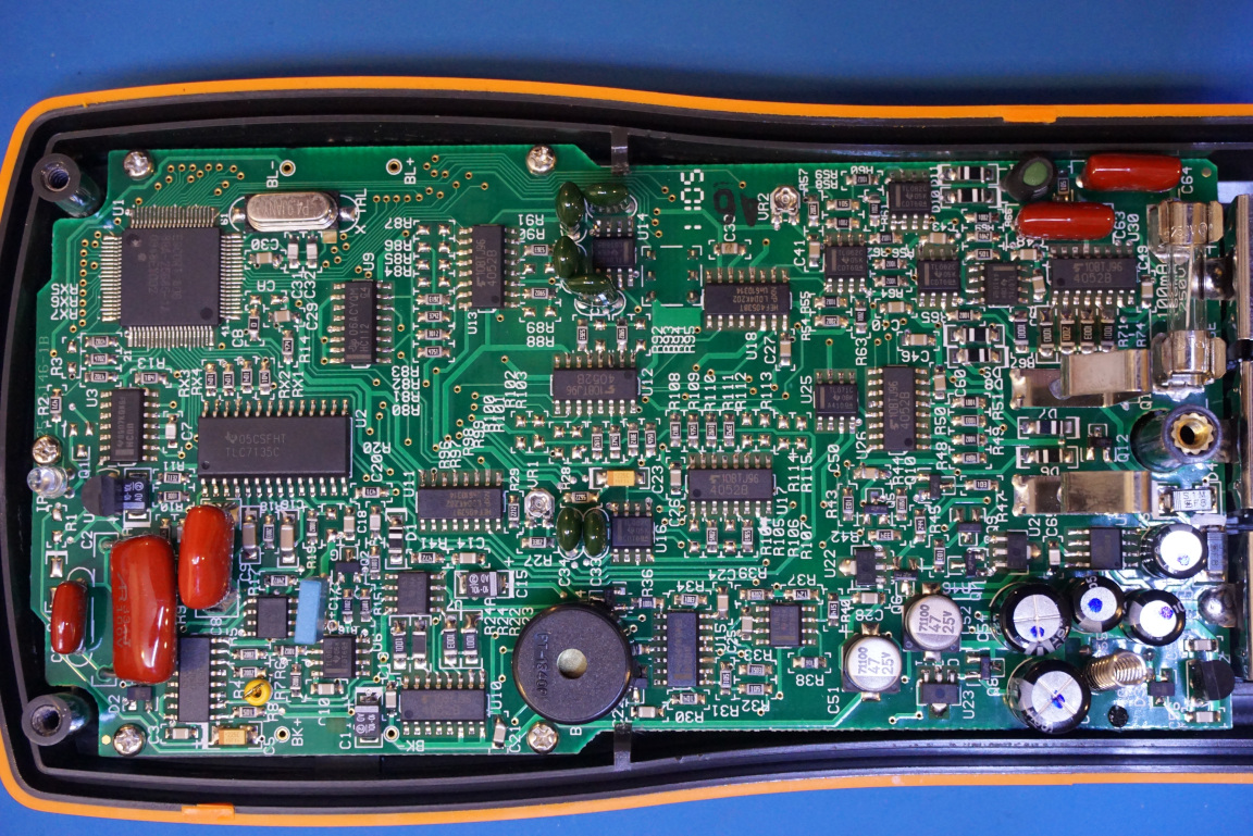
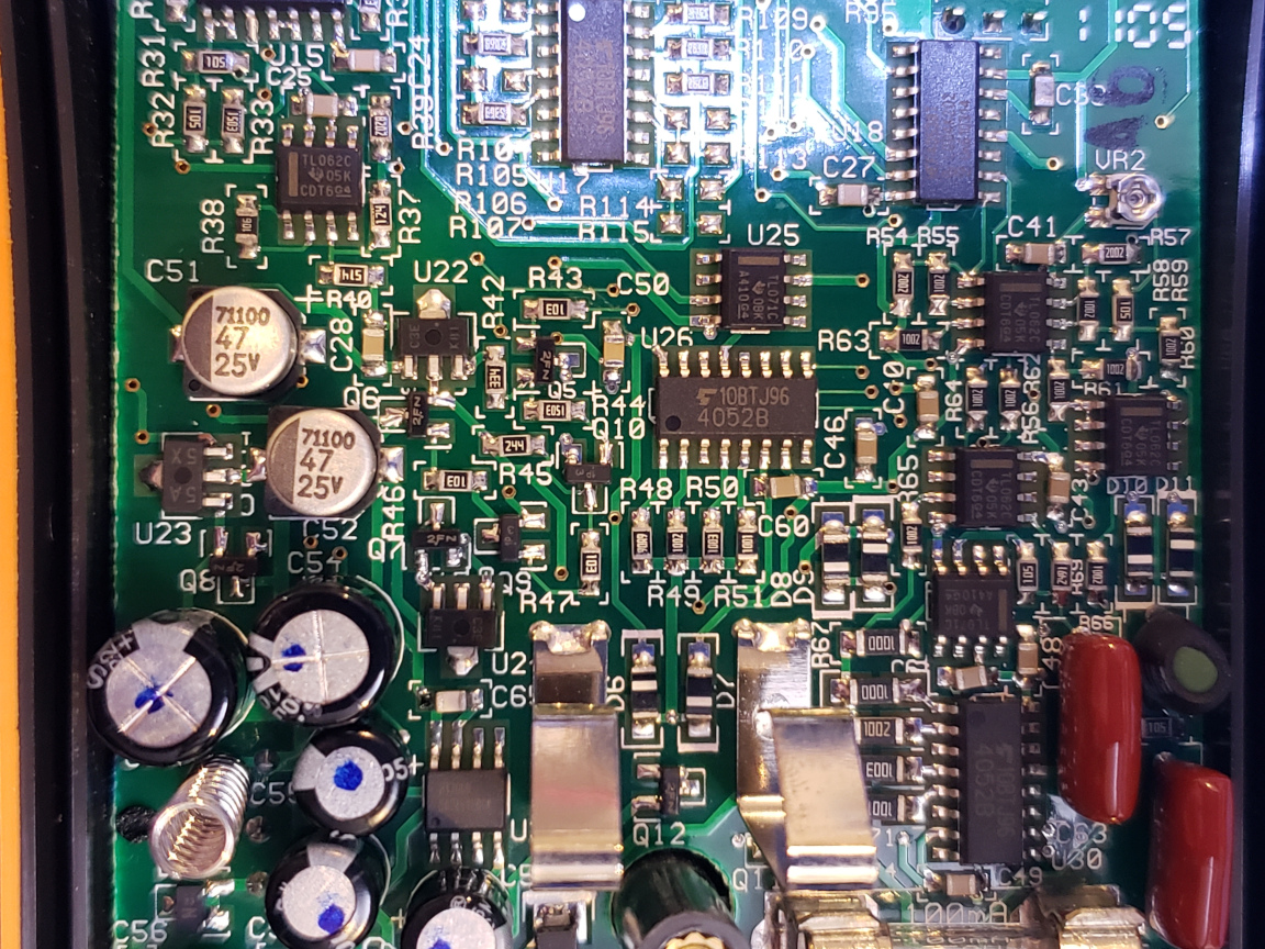
The first thing that strikes me is that how densely populated the PCB is. It is not that the meter contains any large pin-count VLSI chips, it is the sheer number of the lower integration density chips that made the components count rather significant.
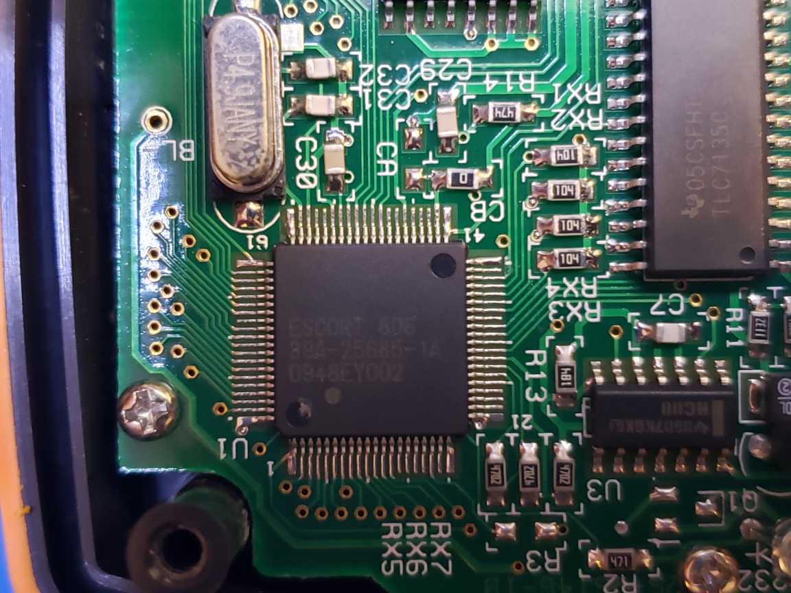
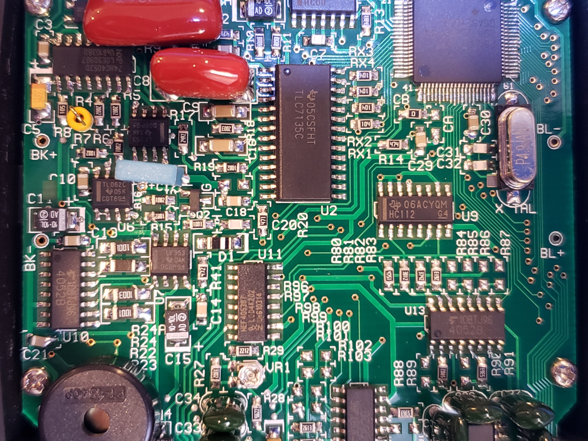
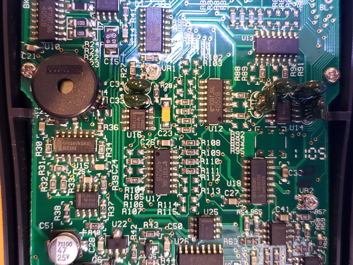
From the two pictures below, you can see that the MCU used in this meter is an ESCORT 39A-25685-1A microcontroller. Although I could not find any information on this specific chip, it would have to be an 8 bit MCU with integrated LCD controller if the MCU used in U1733C is of any guidance (the MCU used in U1733C is a Renesas 78F0485). The ADC used in this meter is a TLC7135C 4½ analog to digital converter.
In later versions of the Agilent U17XX series, a 24 bit ADC chip (ADS1243) is used, which is a significant improvement over the TLC7135C.
|
|
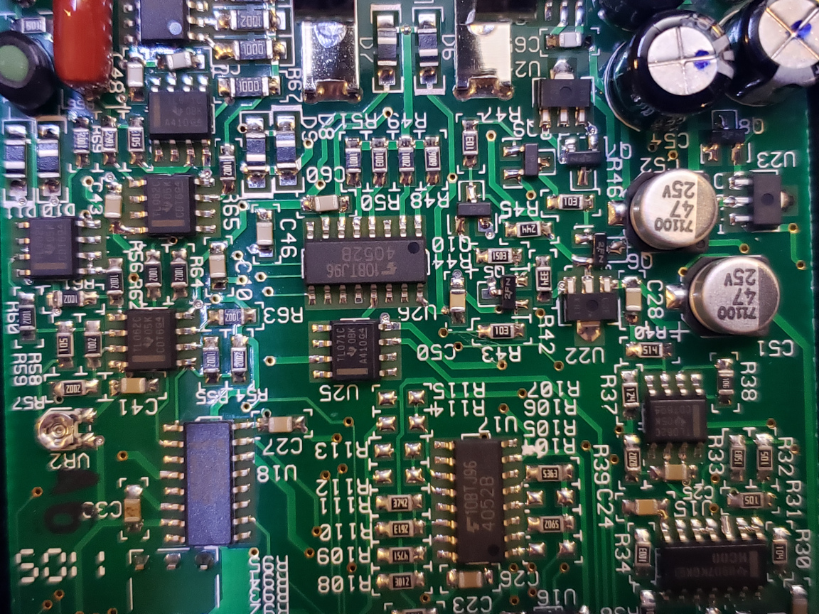
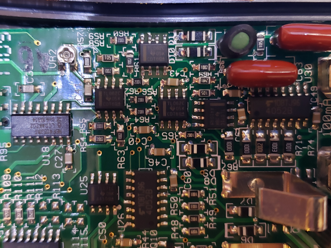
As you can see in the pictures below, most of the other ICs are OpAmps (TL062, TL071, TL082, LF353), multiplexers/demultiplexers (4052B, 4053D) and some 74 series ICs (74HC112 dual JK flip-flop, 74HC00 quad 2-input NAND).
|
|
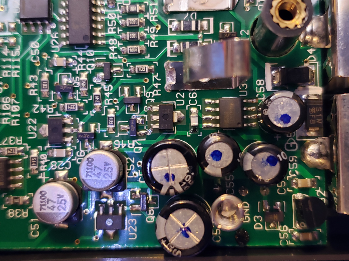
And here are a couple more close-up pictures showing various part of the board. In the picture to the right below, you can just make out the HOLTEK HT7600 switched capacitor voltage converter chip. This chip is used to provide the negative voltages needed by the ADC (TLC7135C) and possibly the OpAmps.
|
|
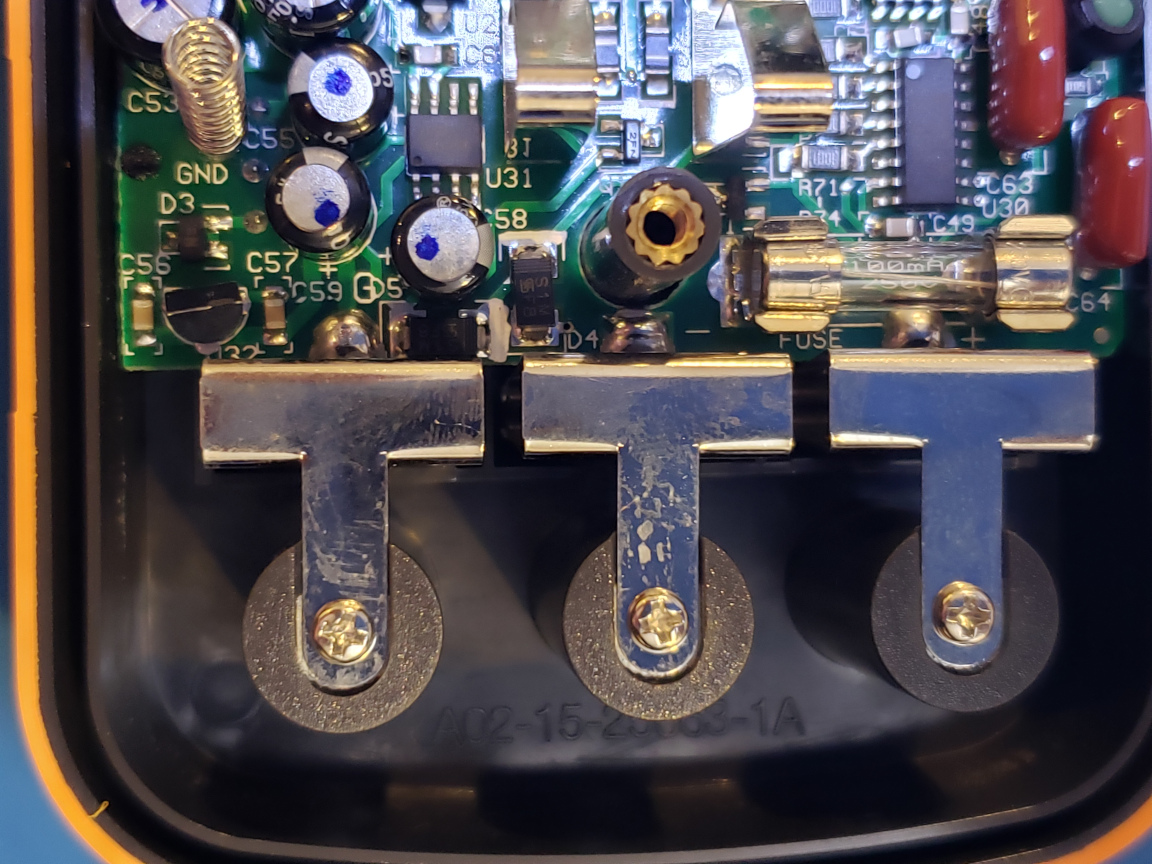
These two pictures below show the input side of things. There is a physical fuse and a PTC for input protection. As Dave pointed out in his video, the protection circuitry changed quite a bit in later models. The physical fuse was replaced with resettable polyfuses and additional PTCs were added for improved protection.
|
|
This meter offers both series mode and parallel mode measurement. The mode that is suitable for a particular measurement depends largely on the impedance of the component being measured. As a rule of thumb (for details please take a look at this application note):
Series mode should be used where the DUT impedance is relatively low. For instance:
small resistance
small inductance
large capacitance
And parallel mode should be used where the DUT impedance is relatively high. For example:
large resistance
large inductance
small capacitance
Here is a video showing the teardown along with some discussion on what mode and test frequency to use for the specific component involved.

